
Safety valve

A technology for safety valves and pilot valves, which is applied in the field of safety valves, and can solve problems such as damage to the sealing surface of the main valve core and the main valve seat, damage to the sealing surface of the main valve core, impact and collision, etc., to ensure opening and closing, and avoid sealing surface damage. Damage, Avoid Impact Collision Effects

Active Publication Date: 2020-02-25
武汉伊斯坎机电技术有限公司
View PDF5 Cites 0 Cited by
  • Summary
  • Abstract
  • Description
  • Claims
  • Application Information

AI Technical Summary

Problems solved by technology

However, in the process of processing and assembly, due to the accumulation of errors, sometimes the concentricity of the main valve core and the main valve seat will deviate, resulting in insensitivity of the main valve movement, and thus the safety valve cannot be opened smoothly under the rated pressure
In addition, when the main spool is opened, there will be impurities attached to the sealing surface of the main spool, and the presence of impurities will lead to poor sealing of the main spool when it is closed, and will affect the sealing of the main spool and the main valve seat. In addition, the main valve core will collide with the sealing surface of the main valve seat when it is opened and closed, which will further damage the sealing surface of the main valve core and the main valve seat and affect the service life.
In addition, when the traditional pilot-operated safety valve is working, the opening and closing action of the main valve is usually relatively rapid, resulting in a large pressure shock, which will bring a great burden to the system where it is located and cause system losses. Affect the service life of the system

Method used


Image

  • Safety valve
  • Safety valve
  • Safety valve

Examples


Embodiment Construction

[0029] The technical solutions of the present invention will be further described in detail below in conjunction with the accompanying drawings and embodiments.

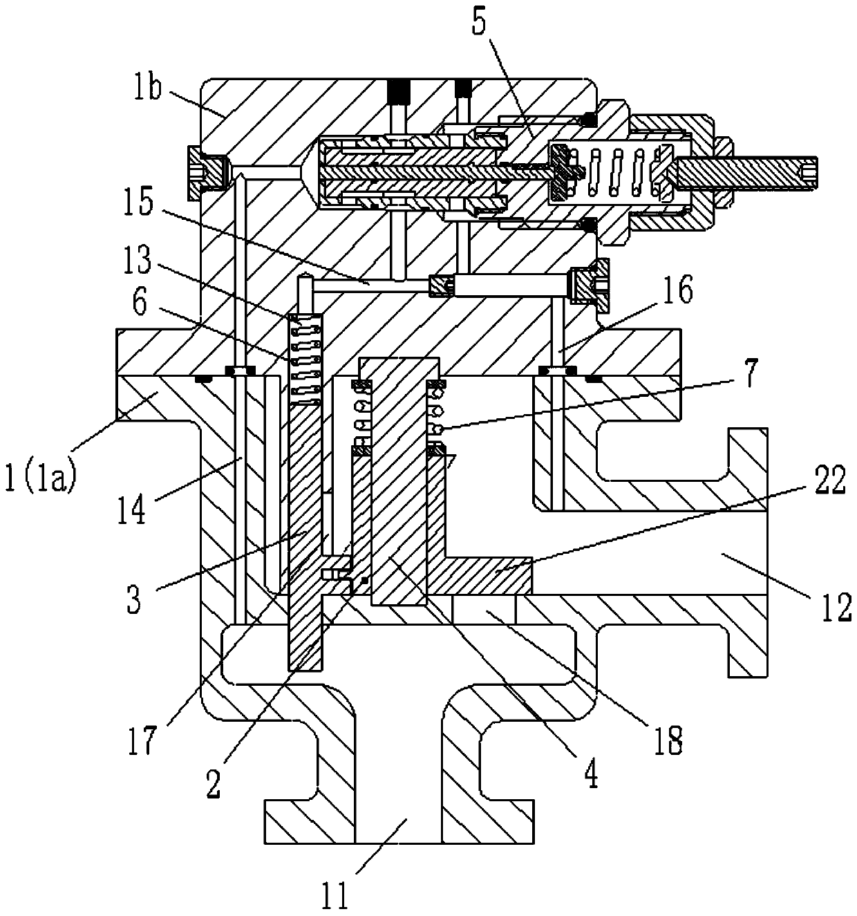
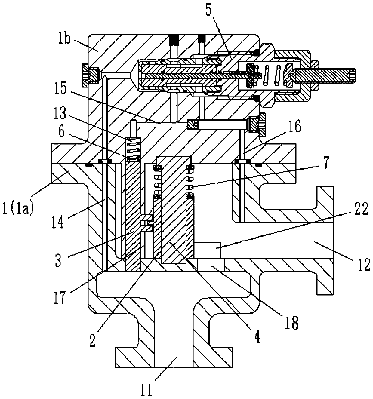
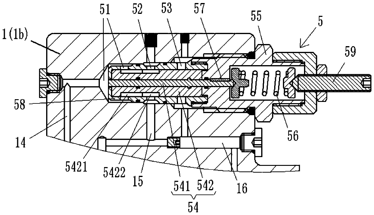
[0030] combine Figure 1 to Figure 3 As shown, the safety valve of this embodiment includes a main valve body 1 , a main valve core 2 , a main valve control rod 3 , a rotating shaft 4 and a pilot valve 5 . Wherein, the pilot valve 5 is inserted and fixed on the main valve body 1, and the main valve body 1 is provided with an oil inlet 11, an oil outlet 12, a control hole 13, a first oil hole 14, a second oil hole 15 and a first oil hole 15. Three oil holes 16.

[0031] The pilot valve 5 is provided with a pilot oil port 51 , a control oil port 52 , an oil return port 53 and a pilot spool 54 . The pilot spool 54 is used to control the closing between the pilot oil port 51 and the control oil port 52, the control oil port 52 and the oil return port 53, and the control between the pilot oil port 51 and the control oil...


PUM


Abstract

The invention belongs to the technical field of industrial valves, and discloses a safety valve which includes a main valve body, a main valve core, a main valve control rod and a rotating shaft. Themain valve control rod and the rotating shaft are arranged in parallel and are both connected to the main valve body, wherein the main valve control rod can move relatively in an axial direction and is provided with a clamping groove, the main valve core sleeves the rotating shaft and is provided with a shield cover and a guide rail, the guide rail is spirally and axially arranged along the outersurface of a guide sleeve and penetrates through the clamping groove, and through the connection between the guide rail and the clamping groove, the main valve core rotates around the rotating shaft with the axial movement of the main valve control rod, so that the shield cover is driven to carry out open and close control over a main channel between an oil inlet and an oil outlet in a horizontaldirection. According to the safety valve, the main valve core can be prevented from being stuck due to concentricity, the smooth operation of the overflow action is ensured, the protection of a sealing surface is improved, the opening and closing impact is reduced, the service life of the entire safety valve is prolonged, and the work stability is improved.

Description

technical field [0001] The invention belongs to the technical field of industrial valves, and in particular relates to a safety valve. Background technique [0002] Pilot-operated safety valve is the best overpressure protection device for pressurized equipment, containers or pipelines, and is mainly used in petroleum, chemical, electric power, metallurgy and other fields. However, during the process of processing and assembling the safety valve, its subsequent actual use performance will be affected due to various reasons. [0003] At present, in conventional pilot-operated safety valves, the opening and closing action of the safety valve is realized by the relative axial movement between the main valve core and the main valve seat on the same axis. However, in the process of processing and assembly, due to the accumulation of errors, sometimes the concentricity of the main valve core and the main valve seat will deviate, resulting in insensitivity of the main valve moveme...

Claims


Application Information

Patent Timeline
Patent Type & Authority Applications(China)
IPC IPC(8): F16K17/164F16K3/06F16K31/383
CPCF16K17/164F16K3/0209F16K3/0254F16K3/06F16K31/383
Inventor 黄延军邵玉刚
Owner 武汉伊斯坎机电技术有限公司
Learn More