Method for treating waste cutting fluid

A waste cutting fluid and waste water technology, applied in filtration treatment, multi-stage water treatment, water/sewage treatment, etc., can solve the problems of sharp material damage on the film surface, secondary pollution, long treatment time, etc.

Inactive Publication Date: 2020-02-25
张伟民 +2
View PDF0 Cites 0 Cited by
  • Summary
  • Abstract
  • Description
  • Claims
  • Application Information

AI Technical Summary

Problems solved by technology

Therefore, unless the manufacturer of waste cutting fluid recycling can also completely treat the waste cutting fluid taken away, this three-stage construction method only achieves part of the "recycling economy" index, but in general, There will still be secondary pollution problems, this is still not a complete solution
[0007] In addition to the above-mentioned three-stage treatment methods, there are different methods used to treat waste cutting fluid on the market, but according to their operating principles, these different methods can be summarized as 1). Evaporation concentration + thermochemical or incineration method , its operating principle is to use evaporation to remove the water from the waste cutting fluid, and then use chemical or incineration methods to treat the residual waste cutting oil. This method requires simple equipment, but its disadvantage is that it cannot recycle useful resources Reuse, and whether it is incineration or thermochemical treatment of waste cutting oil, there are doubts about causing secondary pollution; 2). Membrane separation method, the principle is to use a filter with a pore size as small as 3~5 nanometers (3~5 Nanometer) Membrane, the waste cutting fluid that has been separated from solid and liquid is sent through these ultrafiltration membranes or reverse osmosis membranes at high pressure, allowing water to pass through the membranes, but allowing oil and impurities to remain on the membranes to achieve the purpose of water purification. The equipment of the first method is precise, but its disadvantage is that the ultrafiltration or reverse osmosis membrane is expensive, and the waste cutting fluid needs to be fed into the membrane by high pressure during operation, and the high power consumption is its main disadvantage. Neither ultrafiltration membrane nor reverse osmosis membrane can retain dissolved heavy metals, and the surface of the membrane is easily damaged by sharp objects, which will also make the overall operation cost high. The above are its main disadvantages
3). Biological treatment method, as the name suggests, is to use artificially cultivated microorganisms (Bio Culture) to eliminate COD and BOD in waste cutting fluid 5 , and bacteria that form suspended jelly, and according to the types and properties of bacteria that cause pollution in waste liquid, this microbial treatment method can be divided into three different microbial methods: anaerobic, aerobic and facultative. The principle of the first method is simple, but the problem is that it takes a long time to process, and it needs to be processed in batches, otherwise the effect is not ideal; moreover, due to changes in seasons and water temperature, these Bio Cultures will also undergo qualitative changes, making the processing process difficult to control , is the main disadvantage of its
4). Adsorption method, as the name suggests, is to lay adsorption materials in the adsorption tank, such as "anthracite", "activated carbon", or "volcanic rock" and other adsorption materials, and then send the waste cutting fluid through the adsorption tank. , can absorb the harmful substances in it; the operation principle of using adsorption method to treat waste cutting fluid is simple and feasible, but since the adsorption material is a consumable and is also part of the operation cost, and the replacement of the consumable also requires labor costs, so if there is no other front It is inevitable and unacceptable that the operation cost of this construction method is too high

Method used


Image

  • Method for treating waste cutting fluid
  • Method for treating waste cutting fluid
  • Method for treating waste cutting fluid

Examples


Embodiment Construction

[0090] The technical solutions in the embodiments of the present invention are clearly and completely described below in conjunction with the drawings in the embodiments of the present invention. In the following description, a lot of specific details are set forth in order to fully understand the present invention, but the present invention can also be implemented in other ways different from those described here, and those skilled in the art can do it without departing from the meaning of the present invention. By analogy, the present invention is therefore not limited to the specific examples disclosed below.

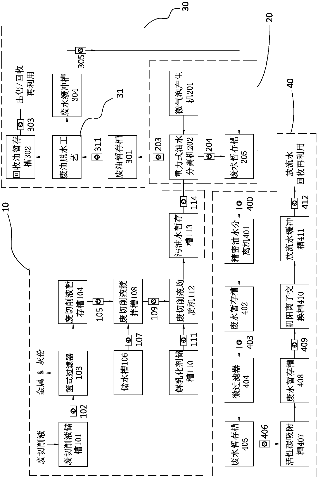
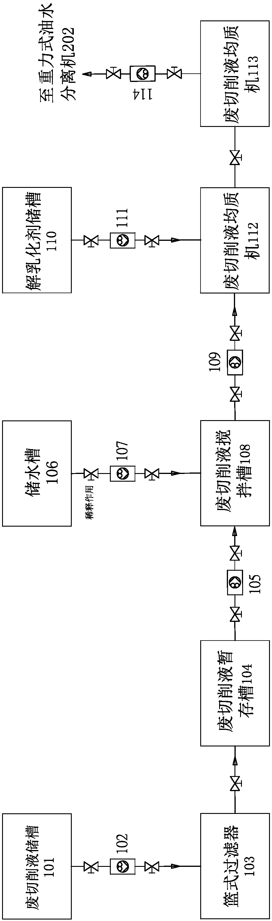
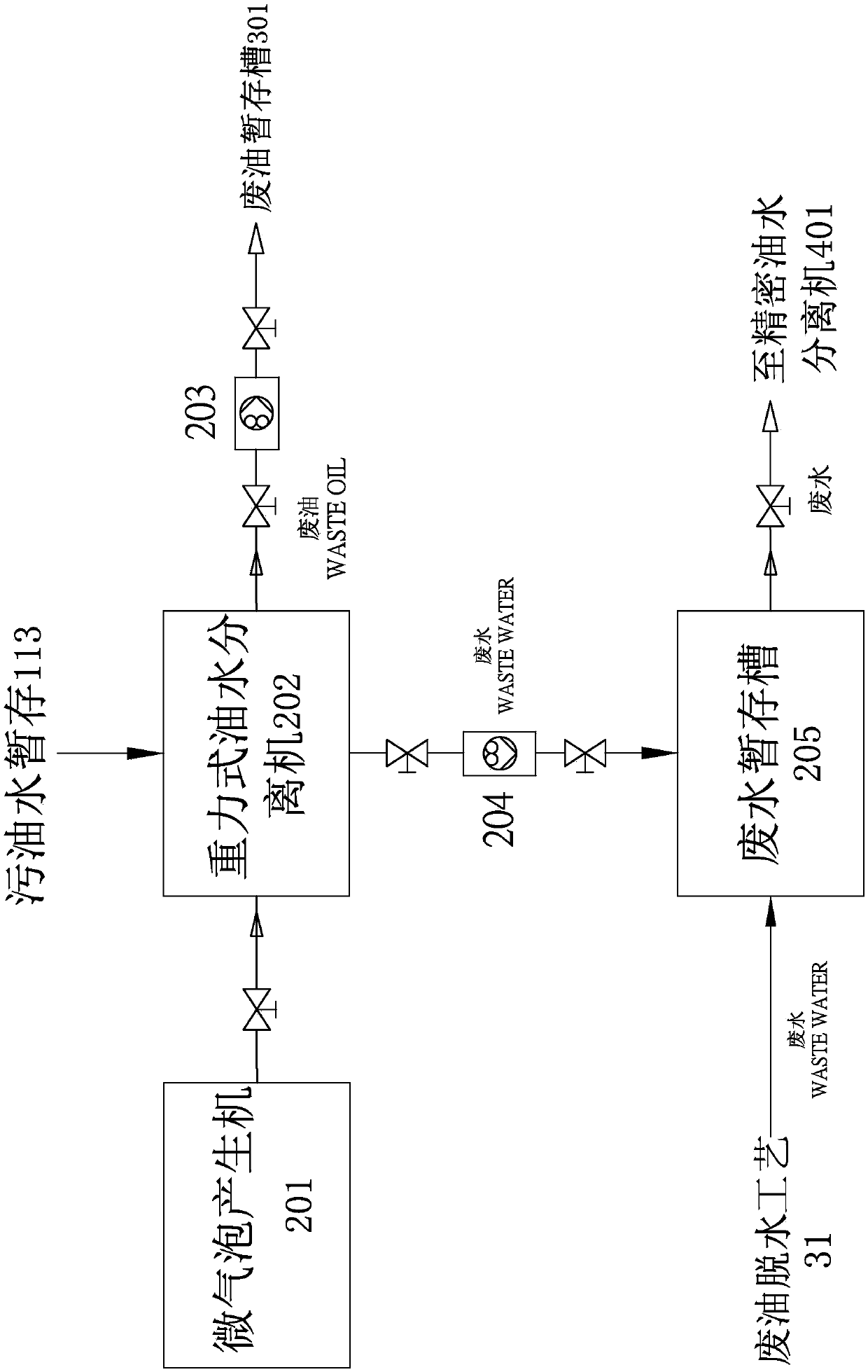
[0091] see figure 1 , figure 2 , is an embodiment of a method for treating waste cutting fluid in the present invention, the method includes a waste cutting fluid deslagging and demulsification step 10, a gravity oil-water separation step 20, a waste oil dehydration step 30, a wastewater treatment Step 40, the waste cutting fluid deslagging and demulsification st...


PUM


Abstract

The invention relates to a method for treating waste cutting fluid. The method comprises: residue removal and demulsification of a waste cutting fluid at a first stage: pre-treating a waste cutting fluid to achieve a waste cutting fluid with stable physical properties; gravity type oil-water separation at a second stage: changing the waste cutting fluid into two materials with different polarities, ie., waste oil and wastewater by using a group of oil-water separators provided with waved plate modules and assisted by suspension gas as a core, and separately conveying the waste oil and the wastewater to the next stage so as to be treated; waste oil dehydration at a third stage: removing the water from the oil material by using a group of bubble type adsorption dehydration devices, so that the recovered oil becomes a valuable recovered material; and wastewater treatment at a fourth stage: clearing the oil, the odor, the heavy metals and the suspended solids contained in the wastewater soas to be recycled or directly released.

Description

technical field [0001] The invention relates to a method for processing waste cutting fluid, in particular to a method for processing waste water-soluble emulsified cutting fluid. Background technique [0002] In order to avoid damage to the workpiece caused by the high temperature generated by the friction between the workpiece and the tool during operation, the cutting fluid is sprayed on the contact surface of the tool and the workpiece during the machining operation to reduce the heating of the workpiece and the wear of the tool. [0003] According to the nature of the workpiece, the cutting fluid used by the operator will be divided into two categories: "water-soluble" and "water-insoluble" according to the polarity; water-soluble cutting fluid is mainly used as a coolant. During machining, spray on the machined surface to avoid qualitative change of the material being processed due to high temperature. Non-water-soluble cutting fluids are mainly lubricated, and the ra...

Claims


Application Information

Patent Timeline
IPC IPC(8): C02F9/04C10M175/04
CPCC02F1/001C02F1/24C02F1/283C02F1/40C02F1/42C02F9/00C02F2001/427C02F2301/08C10M175/04
Inventor 张伟民张正颖张睿庭
Owner 张伟民
Why Eureka
Try Eureka