
Transmission system

A hydraulic transmission and actuator technology, which is applied in fluid pressure actuation system components, fluid pressure actuation devices, medical science, etc., can solve problems such as the lack of robotic systems and the inability to perform delicate surgical tasks effectively and reliably , resulting in improved accuracy and safety

Active Publication Date: 2022-07-19
敦提大学
View PDF11 Cites 0 Cited by
  • Summary
  • Abstract
  • Description
  • Claims
  • Application Information

AI Technical Summary

Problems solved by technology

[0005] However, traditional equipment and techniques still have shortcomings
For example, current robotic systems used in surgery lack entirely or provide very limited tactile feedback to the user, making it impossible to efficiently and reliably perform delicate surgical tasks

Method used


Image

  • Transmission system
  • Transmission system
  • Transmission system

Examples


Embodiment Construction

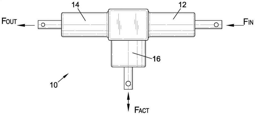
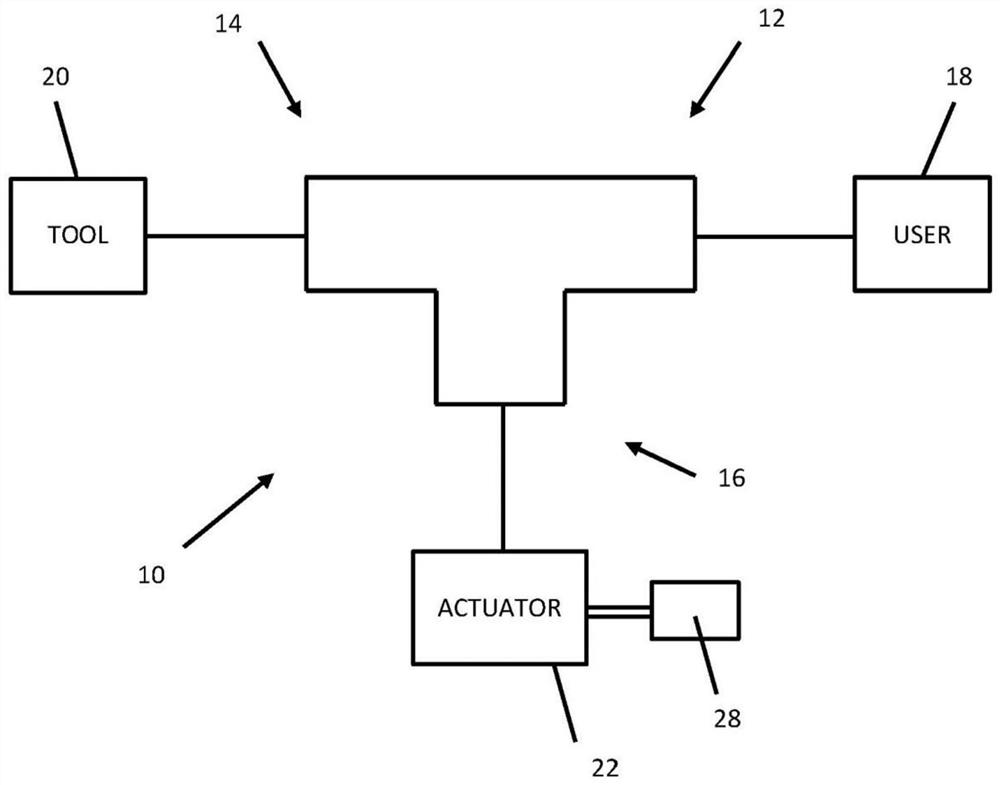
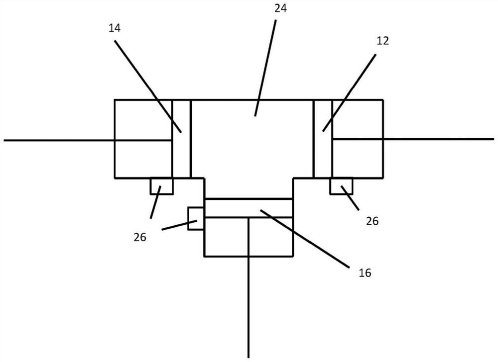
[0054] with reference to the attached figure 1 , the transmission system 10 includes a first piston 12 , a second piston 14 and a regulator piston 16 . Three pistons are used as actuators to transmit force. like figure 1 As shown, the first piston 12 transmits the input force F IN , the second piston 14 transmits the output force F OUT , and the regulator piston 16 transmits the regulating force F ACT . The drive train can be adjusted by using the force F ACT Enhanced input force F IN to achieve tremor cancellation and motion scaling, resulting in an output force F OUT . Adjustment force F is controlled by actuating the adjuster piston 16 ACT to enhance the input force F IN .

[0055] like figure 2 shown, the input force F transmitted by the first piston 12 IN Can be generated by the user 18 (eg, a surgeon). The drive system 10 may be used to control a tool 20 such as a surgical instrument, which in some cases may be an instrument for minimally invasive or lapar...


PUM


Abstract

A transmission system (10) includes a first piston (12), a second piston (14) and a regulator piston (16). The first piston (12) receives the input force (F IN ), the second piston (14) transmits the output force (F OUT ), and the regulator piston (16) transmits the regulating force (F ACT ), which adjusts the input force (F) received by the second piston (14) IN ) to achieve tremor cancellation and induce and / or provide variable motion scaling.

Description

technical field [0001] The present invention relates to a hydraulic transmission system for use in a micromanipulator system. Background technique [0002] A wide variety of work involves micromanipulation, the manipulation of objects on the microscale with precision that is not easily or impossible to achieve by the human body alone. For example, many surgical procedures involve micromanipulation, where the ability to manipulate objects with a high level of control is critical to the success of a given procedure. [0003] In addition to the existing limitations of micromanipulation, a major limiting factor in the adoption of microsurgical techniques and equipment is the presence of physiologic tremors, the involuntary movements of the user due to involuntary muscle contraction and relaxation. Physiological tremors are usually not visible to the naked eye and have little effect in normal daily life. However, it will be appreciated that during tasks such as microsurgery req...

Claims


Application Information

Patent Timeline
Patent Type & Authority Patents(China)
IPC IPC(8): F15B7/00
CPCF15B7/001A61B2017/00539F15B2211/6336F15B2211/8613F15B2211/8616F15B21/008A61B34/30A61B34/76F15B7/08
Inventor 路易吉·曼菲蒂
Owner 敦提大学
Learn More