A flat 180° light-emitting patch led

A technology of LED chips and planes, applied in semiconductor devices, electrical components, circuits, etc., can solve the problems affecting the uniformity of emitted light, the thickness of SMD LEDs, and the poor uniformity of light, so as to improve the diffuse reflection effect and reduce the Thickness, the effect of reducing loss

Active Publication Date: 2020-12-08
宁波纬智光电科技有限公司
View PDF14 Cites 0 Cited by
  • Summary
  • Abstract
  • Description
  • Claims
  • Application Information

AI Technical Summary

Problems solved by technology

[0002] SMD LED is a simple lamp. Its luminous principle is to pass current through compound semiconductors, and through the combination of electrons and holes, the excess energy is released in the form of light to achieve the effect of luminescence. At present, the SMD LED luminous angle Generally, it is around 120°. In order to increase the light-emitting angle, a secondary optical lens is generally installed above the chip to increase the light-emitting area. The focusing effect causes the luminous intensity at the edge to be lower than that in the middle, which affects the uniformity of the emitted light; and when the optical lens is used to improve the luminous effect, the shape and thickness of the optical lens determine the shape of the entire SMD LED And thickness, and when using optical lenses, it is necessary to add light guide plates, light enhancement sheets, etc., which makes the thickness of the entire SMD LED thicker
Therefore, the existing SMD LEDs have the problems of poor light uniformity and thick thickness.

Method used


Image

  • A flat 180° light-emitting patch led
  • A flat 180° light-emitting patch led
  • A flat 180° light-emitting patch led

Examples


Embodiment Construction

[0018] The present invention will be further described below in conjunction with the examples, but not as a basis for limiting the present invention.

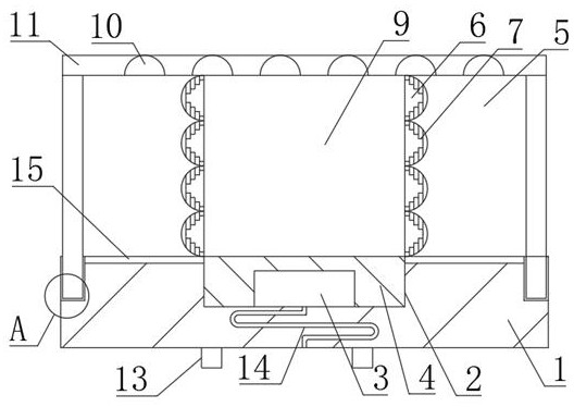
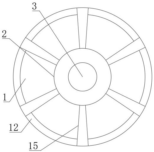
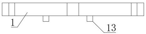
[0019] Example. A flat 180° light-emitting SMD LED, constituted as Figures 1 to 4 As shown, including the bracket 1, the middle part of the bracket 1 is provided with a bowl cup 2; the circumference of the bowl cup 2 is provided with a plurality of uniformly distributed radioactive lines 15, and the bowl cup 2 is provided with LED chips 3, and the bowl cup 2 is provided with LED chips 3. Filled with optical glue 4; the top of the bracket 1 is coated with a diffusion layer 5, and the position of the bowl cup 2 on the diffusion layer 5 is provided with a light outlet 9; There are diffuse reflection grooves 6, and a plurality of protrusions 7 are annularly distributed in each diffuse reflection groove 6; a light outlet is provided at a position corresponding to one end of each radial pattern 15 on the side of the support 1.

[...


PUM


Abstract

The invention discloses a planar 180-degree light-emitting patch LED. The LED comprises a support (1). A bowl cup (2) is arranged in the middle of the support (1). A plurality of radioactive lines (15) are annularly arranged on a circumference of the bowl cup (2). An LED chip (3) is arranged in the bowl cup (2), and the bowl cup (2) is filled with an optical cement (4). A diffusion layer (5) is coated above the support (1). A light outlet hole (9) is arranged in the diffusion layer (5) at a position of the bowl cup (2). A plurality of diffuse reflection grooves (6) are arranged in two side walls of the light outlet hole (9), and a plurality of embossments (7) are annularly distributed in each diffuse reflection groove (6). A light outlet is arranged in the position, corresponding to one end portion of each radioactive line (15), of the side surface of the support (1). In the invention, light uniformity can be improved, and the LED has advantages of a small thickness, high design flexibility, a high light source lighting effect, a wide application range, a long service life, a good heat dissipation effect and high flame-retardant performance.

Description

technical field [0001] The invention relates to an LED light source, in particular to a patch LED that emits light at 180° in a plane. Background technique [0002] SMD LED is a simple lamp. Its luminous principle is to pass current through compound semiconductors, and through the combination of electrons and holes, the excess energy is released in the form of light to achieve the effect of luminescence. At present, the SMD LED luminous angle Generally, it is around 120°. In order to increase the light-emitting angle, a secondary optical lens is generally installed above the chip to increase the light-emitting area. The focusing effect causes the luminous intensity at the edge to be lower than that in the middle, which affects the uniformity of the emitted light; and when the optical lens is used to improve the luminous effect, the shape and thickness of the optical lens determine the shape of the entire SMD LED And thickness, and when using optical lenses, it is necessary ...

Claims


Application Information

Patent Timeline
Patent Type & Authority Patents(China)
IPC IPC(8): H01L33/48H01L33/58H01L33/62H01L33/64
CPCH01L33/486H01L33/58H01L33/62H01L33/64
Inventor 罗副文李高武蔡悦洋王志超
Owner 宁波纬智光电科技有限公司
Why Eureka
Try Eureka