
Full-face tunnelling machine cutter arrangement design method based on stratum conditions

A full-face tunnel boring machine and design method technology, applied in mining equipment, earthwork drilling, instruments, etc., can solve the problem of insufficient certainty of the solution results, no quantitative calculation of the arrangement of the cutters, and no consideration of the rock-breaking efficiency of the cutters Impact and other issues

Active Publication Date: 2020-02-21
NANJING UNIV OF TECH +2
View PDF8 Cites 7 Cited by
  • Summary
  • Abstract
  • Description
  • Claims
  • Application Information

AI Technical Summary

Problems solved by technology

This method does not take into account the impact of formation conditions on tool arrangement
[0007] 3 (Song Tiantian, Zhou Shunhua. Research on shield cutter head design under complex stratum conditions [J]. Journal of Underground Space and Engineering, 2007 (03): 479-482.) Summarized the determination of cutter types and combinations from the perspective of qualitative analysis method, but there is no quantitative calculation method for the arrangement of tools
[0008] 4 (Huo Junzhou, Shi Yanjun, Teng Hongfei, Chai Rongfeng, Zhang Lihua. The Design Method of Tool Arrangement for Full-face Rock Tunneling Machine [J]. China Mechanical Engineering, 2008(15): 1832-1836.) proposed the iteration of tool arrangement However, the calculation method of the polar angle of the tool on the cutter head has multiple solutions, and there is a lack of certainty in the solution results
[0009] 5 (Zhu Dianhua, Sun Bin. Multi-objective optimal layout of TBM positive hob based on balanced rock breaking amount[J]. Mechanical Design, 2017, 34(11):1-6.) Proposed cutter arrangement from the perspective of balanced rock breaking method, but did not consider the impact of cutter arrangement on rock breaking efficiency
[0010] 6 (Zhu Dianhua, Song Liwei, Guo Wei. Theoretical research on the layout design of cutter head and hob for full-face rock tunneling machine based on immune algorithm [J]. Mechanical Design, 2018, 35(11): 31-38.) A cutterhead design method based on tool spacing optimization is proposed based on the number of disk radius strips, but the calculation method for the polar angle of the cutter on the cutterhead is not given

Method used

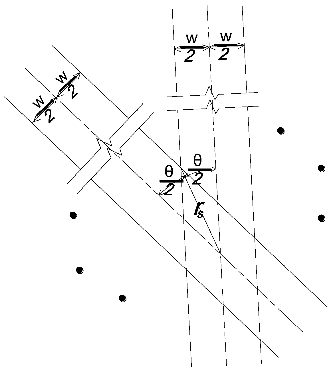
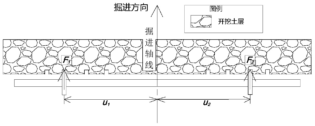
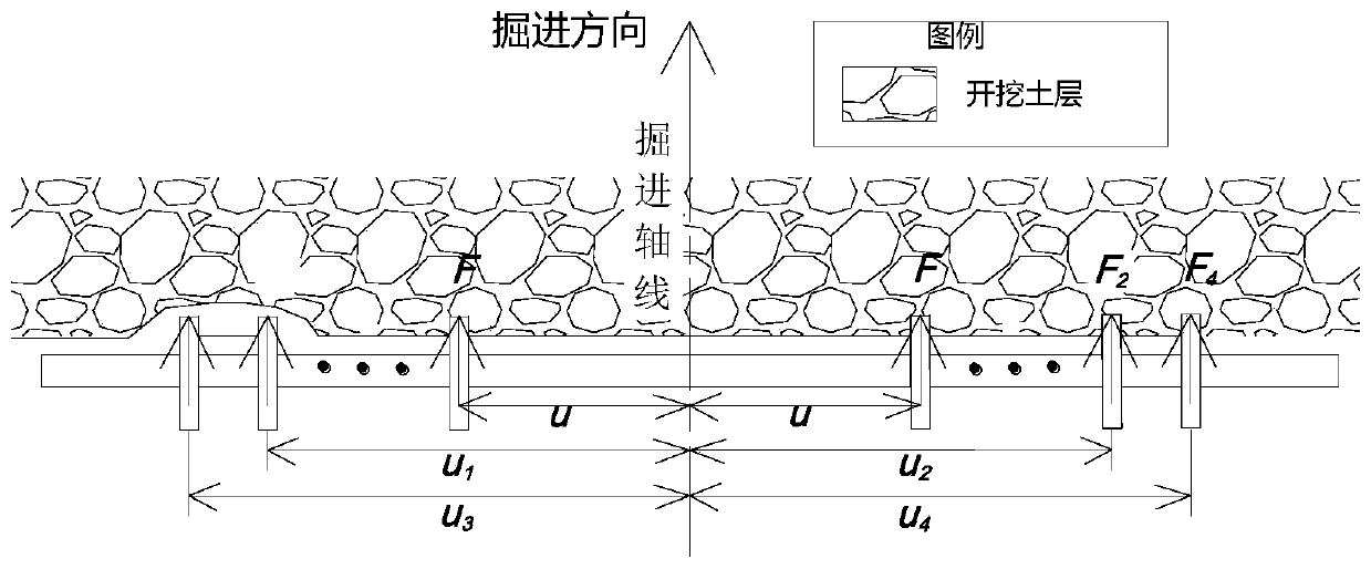

Image

  • Full-face tunnelling machine cutter arrangement design method based on stratum conditions
  • Full-face tunnelling machine cutter arrangement design method based on stratum conditions
  • Full-face tunnelling machine cutter arrangement design method based on stratum conditions

Examples


Embodiment 1

[0182] The face of the tunnel is sandy soil, wr=30%, d s =0.03m, shield machine R=0.5m, B=0.02m, tool w=0.08m, ct=0.01m, θ 1 = 0, ρ 1 = 70mm.

[0183] According to formula (6), it is calculated that θ≥13.586°, and the corresponding c max for 26.

[0184] to c max =26 checks: according to formula (1) and formula (2), c max = 26 hours r s =4.15×0.08=0.332m, R-B-r s =0.148m>l min =4.65×0.03=0.1395m, so c in step 4 max =26.

[0185] According to formula (7), s'=106mm.

[0186] According to formula (10), Then N s1 =6.

[0187] According to formula (11), N s =6.

[0188] According to formula (12),

[0189] According to step 4, when c max >N s hour,

[0190] According to formula (13), formula (14), formula (15) and step 4, table 3 is obtained.

[0191] Table 3 The results of the cutter layout design of Example 1

[0192]

[0193]

[0194] According to step 5, each tool satisfies formula (21), so the tool arrangement design is as follows Figure 10 sho...

Embodiment 2

[0196] The working face is moderately weathered tuff interbedded with pebble layers, R c =24MPa, d s =0.3m, shield machine R=1m, B=0.1m, cutter w=0.1m, ct=0.02m, θ 1 = 1, ρ 1 =80mm.

[0197] According to formula (6), it is calculated that θ≥31°, and the corresponding c max for 10.

[0198] to c max =10 to check: according to formula (1) and formula (2), c max = 10 o'clock r s =1.62×0.1=0.162m, R-B-r s =0.738m>l min =2.12×0.3=0.636m, so c in step 4 max =10.

[0199] According to formula (8), s'=92mm.

[0200] According to formula (10), Then N s1 =11.

[0201] According to formula (11), N s =12.

[0202] According to formula (12),

[0203] According to step 4, when c max s hour,

[0204] According to formula (16), formula (17), formula (18), formula (19), formula (20) and step 4, get Table 4.

[0205]The cutter layout design result of table 4 embodiment 2

[0206]

[0207]

[0208] According to step 5, each tool satisfies formula (21), so the tool...

Embodiment 3

[0210] The face of the face is moderately weathered granite layer, R c =60MPa, d s =0.12m, shield machine R=0.3m, B=0.05m, tool w=0.12m, ct=0.02m, θ 1 = 0, ρ 1 = 60mm.

[0211] According to formula (6), it is calculated that θ≥78.34°, and the corresponding c max for 4.

[0212] to c max =4 is checked: according to formula (1) and formula (2), c max = 4 o'clock r s =0.71×0.12=0.0852m, R-B-r s =0.1648m>l min =1.21×0.12=0.1452m, so c in step 4 max =4.

[0213] According to formula (9), s'≈84.5mm.

[0214] According to formula (10), Then N s1 =4.

[0215] According to formula (11), N s =4.

[0216] According to formula (12),

[0217] According to step 4, when c max =N s hour,

[0218] According to formula (13), formula (14), formula (15) and step 4, table 5 is obtained.

[0219] Table 5 The results of the cutter arrangement design of the third embodiment

[0220]

[0221] According to step 5, each tool satisfies formula (21), so the tool arrangement d...


PUM

PropertyMeasurementUnit
Thicknessaaaaaaaaaa

Abstract

The invention provides a full-face tunnelling machine cutter arrangement design method based on actual stratum conditions, and relates to the technical field of full-face tunnelling machine cutter head design. The method comprises the following steps of calculating the adjacent spoke overlapping diameter of a cutter head according to the cutter mounting width; determining the optimal cutter head scroll number according to the muck particle trafficability; determining the number of cutters according to the stratum parameters; calculating the tool arrangement Archimedes spiral parameters in a classified mode; and checking and adjusting the cutter layout contradiction. According to the method, the efficient rock breaking and continuous soil discharging operations of a hob can be guaranteed, and the overall torque balance degree of the cutter head is effectively improved. The method is a cutter head design method considering the actual stratum situations, the calculation principle is clear, and the calculation process is simple and clear.

Description

technical field [0001] The invention relates to the technical field of cutter head design of a full-section tunnel boring machine, in particular to a method for designing the cutter arrangement of a full-section tunnel boring machine based on stratum conditions. [0002] technical background [0003] The full-face tunnel boring machine crushes and cuts the surrounding rock through the interaction between the cutter and the tunnel face. The cutter head is the carrier of the cutter. After the surrounding rock is crushed and cut, it forms muck particles, which pass through the cutter head The opening area of ​​the cutter head enters the area behind the cutter head and is transported out of the ground to realize continuous excavation. The arrangement of the cutters on the cutterhead is the main content of the cutterhead design, and a good cutter arrangement design can effectively improve the tunneling efficiency. [0004] The currently existing cutterhead design methods are: ...

Claims


Application Information

Patent Timeline
IPC IPC(8): G06F30/17G06F119/14E21D9/11
CPCE21D9/11
Inventor 李彤韩爱民施烨辉程荷兰韩如碧张世豪苏明陈冬翟维骏张心远李璇王金铭李闯黄凌莉
Owner NANJING UNIV OF TECH
Learn More