
Sludge blending system for scraper slag extractor

A slag scraper and scraper technology, applied in the field of sludge blending and burning system, can solve the problem of inability to recover the heat of high-temperature slag, and achieve the effect of convenient measurement

Active Publication Date: 2021-08-24
CHINA ENERGY ENG GRP GUANGDONG ELECTRIC POWER DESIGN INST CO LTD
View PDF8 Cites 0 Cited by
  • Summary
  • Abstract
  • Description
  • Claims
  • Application Information

AI Technical Summary

Problems solved by technology

[0006] In order to solve the above problems, the object of the present invention is to provide a sludge blending system for the scraper slag extractor to solve the problem that the structure of the existing scraper slag extractor and boiler cannot recover the heat of high-temperature slag

Method used


Image

  • Sludge blending system for scraper slag extractor
  • Sludge blending system for scraper slag extractor

Examples


Embodiment Construction

[0020] The specific implementation manners of the present invention will be further described in detail below in conjunction with the accompanying drawings and embodiments. The following examples are used to illustrate the present invention, but are not intended to limit the scope of the present invention.

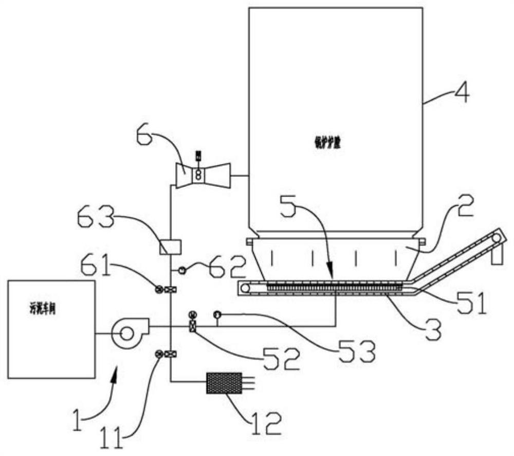
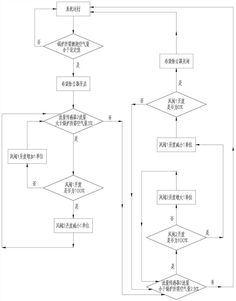
[0021] combine figure 1 and figure 2 As shown, the sludge co-combustion system for the scraper slag extractor of the present invention is schematically shown, including an exhaust gas source 1 , a slag extraction chamber 2 and a scraper slag extractor 3 . The slag removal chamber 2 is located below the boiler furnace 4, and the bottom of the boiler furnace 4 is connected to the top of the slag removal chamber 2. Of course, a fuel support bracket can be set between the boiler furnace 4 and the slag removal chamber 2 as required (the fuel includes but Not limited to coal and sludge), the support frame is provided with multiple hollow structures, and when the fuel is burne...


PUM


Abstract

The invention relates to the field of thermal power generation, in particular to a sludge blending system for a scraper slag remover. The slag extraction machine is located in the slag extraction room. The high-temperature slag produced by the combustion of the boiler furnace falls into the slag extraction room under the action of gravity for temporary storage and immersion cooling. The nozzles are sprayed out to meet the air intake requirements at the bottom of the boiler furnace, and the amount of air injected by the nozzles is controllable and easy to measure. At the same time, the exhaust gas emitted by the nozzles can also cool the liquid in the scraper slag machine Send heat back to the boiler furnace to reduce the temperature of the liquid in the scraper scraper.

Description

technical field [0001] The invention relates to the field of thermal power generation, in particular to a sludge blending combustion system used in a scraper slag extractor. Background technique [0002] Sludge is a kind of high water content floc composed of various microorganisms and organic and inorganic particles. It is enriched with impurities and salts in the raw water treatment process. Some pollutants can dissolve in water and cause water pollution. Contains a large amount of toxic and harmful substances, if not handled properly, it will cause great damage to the human body and the ecological environment. At present, the commonly used sludge treatment methods include landfill, composting and incineration, etc., and landfill is the main method. The pollution caused by non-standardized sludge treatment and the problem of "secondary pollution" are becoming more and more serious. [0003] Coal-fired thermal power generation is currently the most important form of power ...

Claims


Application Information

Patent Timeline
Patent Type & Authority Patents(China)
IPC IPC(8): F23G7/00F23G5/44F23J1/06F23G5/46
CPCF23G5/44F23G5/442F23G5/444F23G5/46F23G7/001F23G2206/10F23G2207/00F23G2207/112F23G2209/12F23J1/06
Inventor 贾斌谭闻王应江罗宇东万承军吴阿峰
Owner CHINA ENERGY ENG GRP GUANGDONG ELECTRIC POWER DESIGN INST CO LTD
Learn More