
compressor

A compressor and high-pressure technology, applied in the field of compressors, can solve the problems of difficult design and manufacture of double-suction structure, low energy efficiency, insufficient high-frequency capability, etc., and achieve the effects of avoiding deformation, reducing crankshaft temperature, and improving reliability

Active Publication Date: 2019-06-28
GUANGDONG MEIZHI COMPRESSOR
View PDF7 Cites 0 Cited by
  • Summary
  • Abstract
  • Description
  • Claims
  • Application Information

AI Technical Summary

Problems solved by technology

[0002] In the related art, the rotary compressor with high and low pressure separation generally has an air suction channel from the main bearing, and the low-pressure gas is sucked into the air cylinder suction chamber through the main bearing air suction channel. The air channel is feasible, but for the double-cylinder compressor, if the suction hole is set in the main bearing, it can only be a single suction structure, and the double suction structure is more difficult to design and manufacture
The single-intake structure has the problems of insufficient high-frequency capability and low energy efficiency, so generally double-cylinders need a double-intake structure

Method used


Image

  • compressor
  • compressor
  • compressor

Examples


Embodiment Construction

[0033] Embodiments of the invention are described in detail below, examples of which are illustrated in the accompanying drawings. The embodiments described below by referring to the figures are exemplary and are intended to explain the present invention and should not be construed as limiting the present invention.

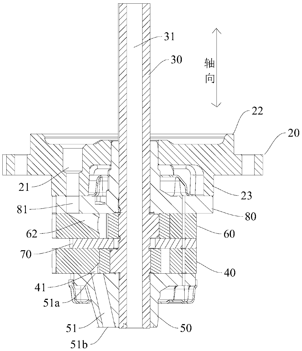
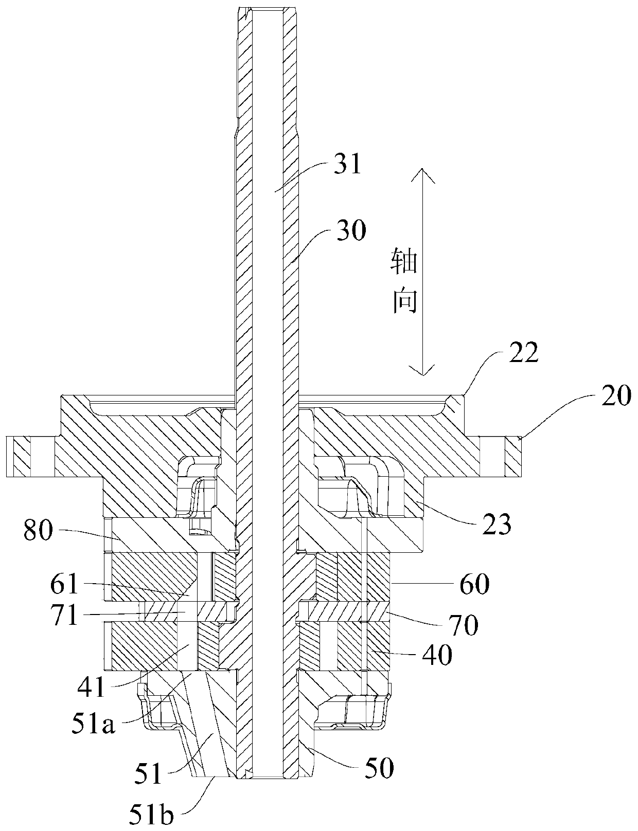
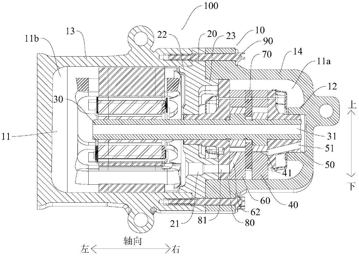
[0034] Refer below Figure 1-Figure 3 The compressor 100 according to the embodiment of the present invention will be described in detail.

[0035] like image 3 As shown, the compressor 100 according to the embodiment of the present invention may include: a casing 10 , a high-pressure and low-pressure separation plate 20 , a crankshaft 30 , a first cylinder 40 and a first bearing 50 .

[0036] like image 3 As shown, an inner cavity 11 can be defined in the housing 10, and the housing 10 can be used to protect internal components and at least to a certain extent can play a role of sealing.

[0037] The high and low pressure partition plate 20 separates the i...


PUM


Abstract

The present invention discloses a compressor which comprises a shell, a high-low pressure separation plate, a crank shaft, a first cylinder, and a first bearing, wherein the shell defines an inner cavity; the high-low pressure separation plate separates the inner cavity in the shell to form a high pressure cavity and a lower pressure cavity; the crank shaft penetrates through the high-low pressure separation plate; two ends of the crank shaft extend to the high pressure cavity and the lower pressure cavity respectively; an inner hole is formed in the crank shaft in a manner of penetrating through the axial direction; the first cylinder is positioned in the high pressure cavity; the crank shaft penetrates through the first cylinder; the first bearing is fixed together with the first cylinder and is close to the end part of the crank shaft; a first air sucking channel is formed in the first bearing and is communicated with the inner hole of the crank shaft and an air inlet of the first cylinder; a coolant in the lower pressure cavity can flow to the air inlet of the first cylinder by the inner hole and the air sucking channel, so that air inlet requirements of the first cylinder in the compressor can be met; in addition, the deformation of the first bearing can be avoided, and the temperature of the crank shaft can be reduced.

Description

technical field [0001] The present invention relates to a compressor. Background technique [0002] In the related art, the rotary compressor with high and low pressure separation generally has an air suction channel from the main bearing, and the low-pressure gas is sucked into the air cylinder suction chamber through the main bearing air suction channel. The air channel is feasible, but for the double-cylinder compressor, if the suction hole is set in the main bearing, it can only be a single suction structure, and the double suction structure is more difficult to design and manufacture. The single-intake structure has the problems of insufficient high-frequency capability and low energy efficiency, so a double-intake structure is generally required for twin cylinders. Contents of the invention [0003] The present invention aims to solve one of the technical problems in the related art at least to a certain extent. For this reason, the present invention proposes a com...

Claims


Application Information

Patent Timeline
Patent Type & Authority Patents(China)
IPC IPC(8): F04C29/12
CPCF04C29/12F04C2240/10F04C2240/50F04C2240/60
Inventor 黎法运杨开成虞阳波
Owner GUANGDONG MEIZHI COMPRESSOR
Learn More