Accurate and efficient realization method and device of linear frequency modulation signal autocorrelation operation
A technology of linear frequency modulation signal and autocorrelation operation, applied in the field of signal processing, can solve the problems of discarding stored data, complex realization structure, and low operation precision, and achieves the effect of no drift in operation precision, fast operation speed, and high operation precision.
- Summary
- Abstract
- Description
- Claims
- Application Information
AI Technical Summary
Problems solved by technology
Method used
Image
Examples
Embodiment 1
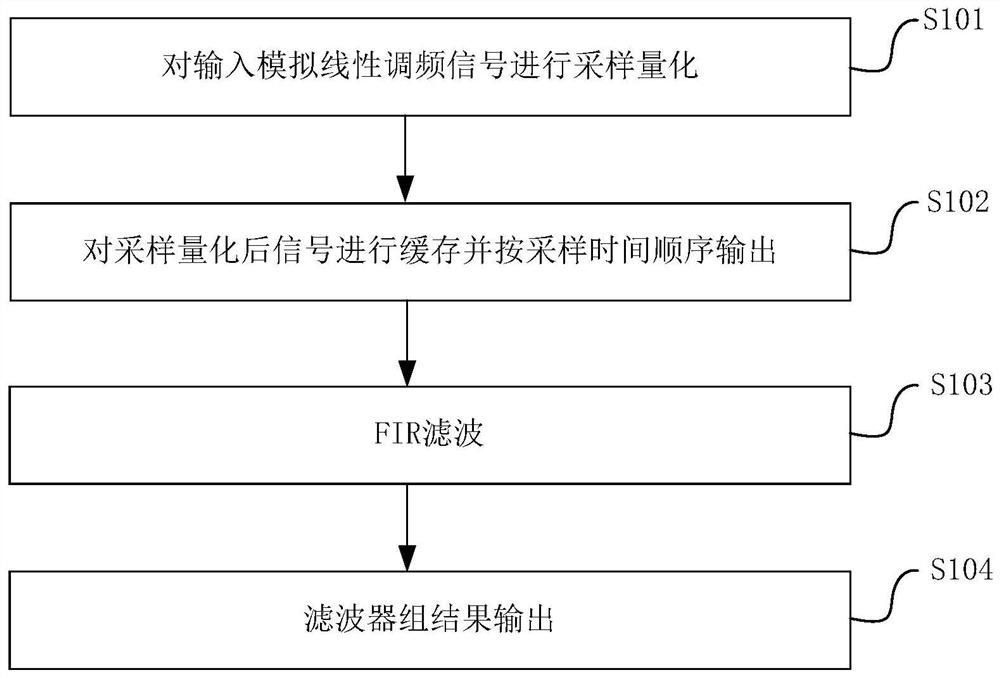
[0040] like figure 1 Shown is a flow chart of an accurate and efficient implementation method for chirp signal autocorrelation operations, and the accurate and efficient implementation method for chirp signal autocorrelation operations includes the following steps:
[0041] In step S101, the input analog chirp signal is sampled and quantized, and the sampling rate is f s , to obtain the digitized N-dimensional signal vector s(n);
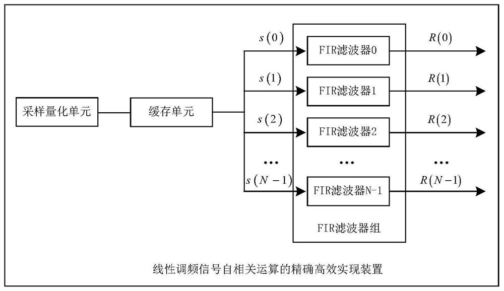
[0042]In step S102, the signal after sampling and quantization is buffered and output to the corresponding FIR filter in the FIR filter bank according to the sampling time sequence, that is, the sampling point s(0) is output to the FIR filter 0, and the sampling point s(1 ) is output to FIR filter 1, sampling point s(2) is output to FIR filter 2, and so on, sampling point s(N-1) is output to FIR filter N-1;
[0043] In step S103, each FIR filter delays the input sampling points (using the signal sampling period as the minimum delay unit to delay s...
Embodiment 2
[0046] This embodiment is similar to Embodiment 1, the difference is that the FIR filter can be implemented by using an FFT (FastFourier Transform, Fast Fourier Transform) algorithm, and the operation speed is relatively fast.
[0047] In addition, memory such as ROM (Read-Only Memory, read-only memory) is used to store the coefficients of the FIR filter bank, and the implementation cost is relatively small.
Embodiment 3
[0049] Corresponding to Embodiment 1 and Embodiment 2, this embodiment sets a finite-length discrete complex LFM signal:
[0050]
[0051] Among them: N is the number of sampling points, the value is a positive integer, n is used to represent the serial number of discrete sampling points, n=0,1,2,...,N-1, f 0 Represents the starting frequency of the complex LFM signal, k represents the frequency modulation slope of the complex LFM signal, f s Indicates the sampling rate, and s(n) indicates the acquired N-dimensional signal vector.
[0052] In the autocorrelation function R(m) of the signal s(n), m is used to represent the delay amount, and the value of m is an integer. When 0≤m≤N-1, the autocorrelation function of the signal s(n) is expressed as:
[0053]
[0054] For the discrete signal s(n), it is numerically the same as s(m), that is, the value of the signal sample with sequence number m can be used to replace s(m) in the above formula. For each determined delay m,...
PUM
 Abstract
Description
Claims
Application Information
 - R&D
- Intellectual Property
- Life Sciences
- Materials
- Tech Scout
- Unparalleled Data Quality
- Higher Quality Content
- 60% Fewer Hallucinations
Browse by: Latest US Patents, China's latest patents, Technical Efficacy Thesaurus, Application Domain, Technology Topic, Popular Technical Reports.
© 2025 PatSnap. All rights reserved.Legal|Privacy policy|Modern Slavery Act Transparency Statement|Sitemap|About US| Contact US: help@patsnap.com


