Radio frequency ultra wide band-driven amplifier chip

A driving amplifier and ultra-broadband technology, which is applied to amplifiers with multiple amplifying components, amplifying control, electrical components, etc., can solve the problems of difficult to increase bandwidth and deteriorate the linearity of driving circuits, etc., and achieve the improvement of phase ratio and Linearity, the effect of optimizing power consumption

Pending Publication Date: 2020-02-14
XIAN BORUI JIXIN ELECTRONICS TECH
View PDF0 Cites 3 Cited by
  • Summary
  • Abstract
  • Description
  • Claims
  • Application Information

AI Technical Summary

Problems solved by technology

However, when the common source amplifier structure is at high frequency, due to the existence of its own parasitic capacitance, it is difficult to improve the bandwidth, and the parasitic capacitance will deteriorate the linearity of the driving circuit.

Method used


Image

  • Radio frequency ultra wide band-driven amplifier chip
  • Radio frequency ultra wide band-driven amplifier chip
  • Radio frequency ultra wide band-driven amplifier chip

Examples


Embodiment Construction

[0024] The present invention will be further described in detail below in conjunction with the accompanying drawings, so that those skilled in the art can implement it with reference to the description.

[0025] It should be understood that terms such as "having", "comprising" and "including" as used herein do not entail the presence or addition of one or more other elements or combinations thereof.

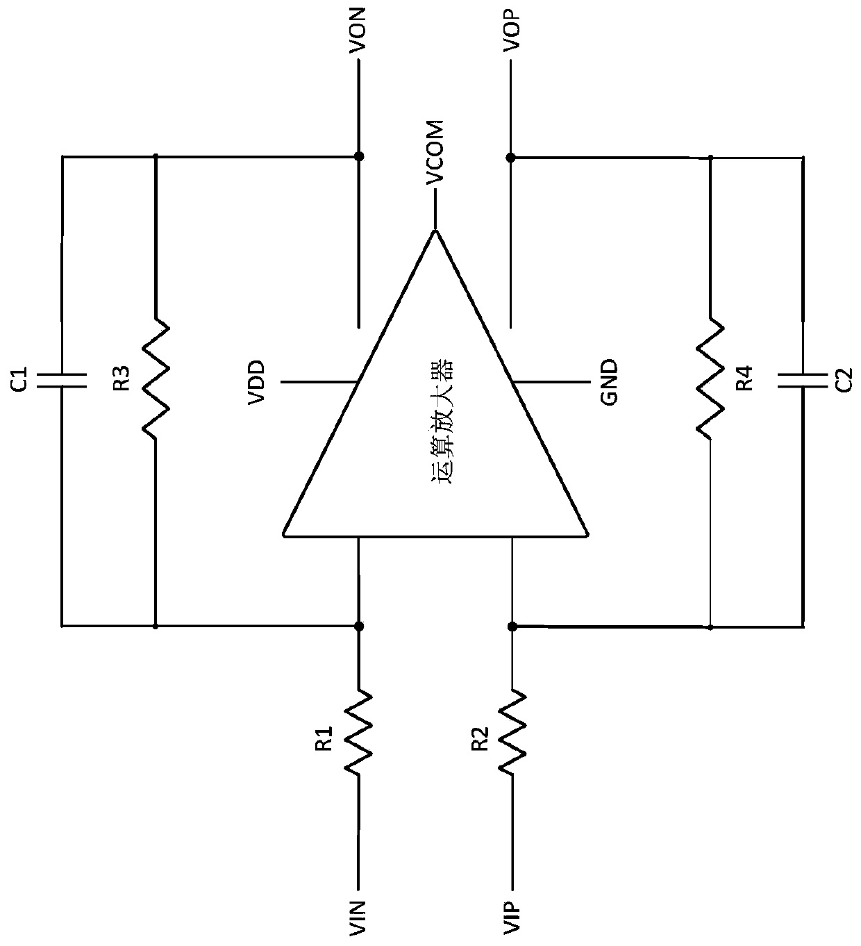
[0026] like figure 1 As shown, the present invention proposes a novel resistance feedback amplifier structure, the circuit structure is that the input signals VIN and VIP are connected to one end of the input resistors R1 and R2, and the other ends of the input resistors are respectively connected to two input ports of the fully differential operational amplifier, And one end of the feedback resistors R3 and R4 is connected to the input port of the amplifier, and the other end of the feedback resistor is respectively connected to the output ports VON and VOP of the amplifier, for...


PUM


Abstract

The invention discloses a radio frequency ultra wide band-driven amplifier chip which comprises two input resistors, two feedback resistors and an operational amplifier. The operational amplifier comprises three amplifiers including a first-stage amplifier, a second-stage amplifier and a third-stage amplifier, the two common-mode feedback circuits comprise a first-stage common-mode feedback circuit and a second-stage common-mode feedback circuit; wherein the first-stage amplifier and the second-stage amplifier are in direct-current coupling, the input end of the third-stage amplifier is connected with the input end of the first-stage amplifier, and the output end of the third-stage amplifier is connected with the output end of the second-stage amplifier to form a feedforward structure; according to the invention, high bandwidth and linearity can be realized, and compared with a traditional two-stage or three-stage amplifier with a compensation capacitor Cc, the amplifier provided by the invention is more suitable for a resistance feedback structure and can realize better performance.

Description

technical field [0001] The invention belongs to the field of radio frequency integrated circuits, and in particular relates to an ultra-wideband drive amplifier chip working in the radio frequency band. Background technique [0002] As a basic module, RF drive amplifier is widely used in various RF integrated systems to improve signal transmission quality and drive capability. With the continuous development and improvement of radio frequency technology, the operating frequency of the chip is getting higher and higher, and the high performance of the radio frequency integrated system is more and more reflected in the higher frequency and broadband, so the requirements for the radio frequency drive circuit are getting higher and higher, the design The difficulty also increases correspondingly, so the study of high-performance RF drive amplifier chips has great application prospects and practical significance. [0003] At present, the more common technologies for designing dr...

Claims


Application Information

Patent Timeline
Patent Type & Authority Applications(China)
IPC IPC(8): H03F3/42H03G3/00
CPCH03F3/42H03G3/00
Inventor 王三路
Owner XIAN BORUI JIXIN ELECTRONICS TECH
Why Eureka
Try Eureka