Twin-bridge fin structure and twin-bridge fin machining die

A fin mold and fin technology are applied in the field of double bridge fin structure and double bridge fin processing mold, which can solve the problems of easy deformation of fin structure, and achieve the effect of improving qualification and continuous processing.

Pending Publication Date: 2020-02-14
黄山三佳谊华精密机械有限公司
View PDF0 Cites 0 Cited by
  • Summary
  • Abstract
  • Description
  • Claims
  • Application Information

AI Technical Summary

Problems solved by technology

[0003] The purpose of the present invention is to provide a double-bridge fin structure and a double-bridge fin processing mold to solve the problem that the existing fin structure is easily deformed when cut

Method used


Image

  • Twin-bridge fin structure and twin-bridge fin machining die
  • Twin-bridge fin structure and twin-bridge fin machining die
  • Twin-bridge fin structure and twin-bridge fin machining die

Examples


Embodiment Construction

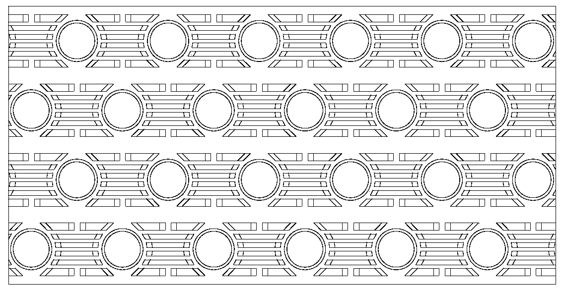
[0023] Examples such as figure 2 As shown, a double bridge fin structure includes at least one row of fin units 1 , and the double bridge fin structure in this embodiment has four rows of fin units 1 arranged side by side. A group of expansion rod installation holes 2 are distributed on each row of fin units 1, and the expansion rod installation holes 2 are equidistantly distributed along the length direction of the fins. The minimum distance for one line is a step.

[0024] Each row of fin units 1 is provided with a first bridge unit 3 or a second bridge unit 4 on both sides of the expansion rod installation hole 2. The double bridge fin structure is installed between the second bridge unit 4 and the expansion rod. Cutting is made between the holes 2 to form a single fin structure. The first bridge unit 3 includes a group of special-shaped bridges 301 with different lengths. The distances are the same, so that the end of the special-shaped bridge piece 301 is surrounded b...


PUM


Abstract

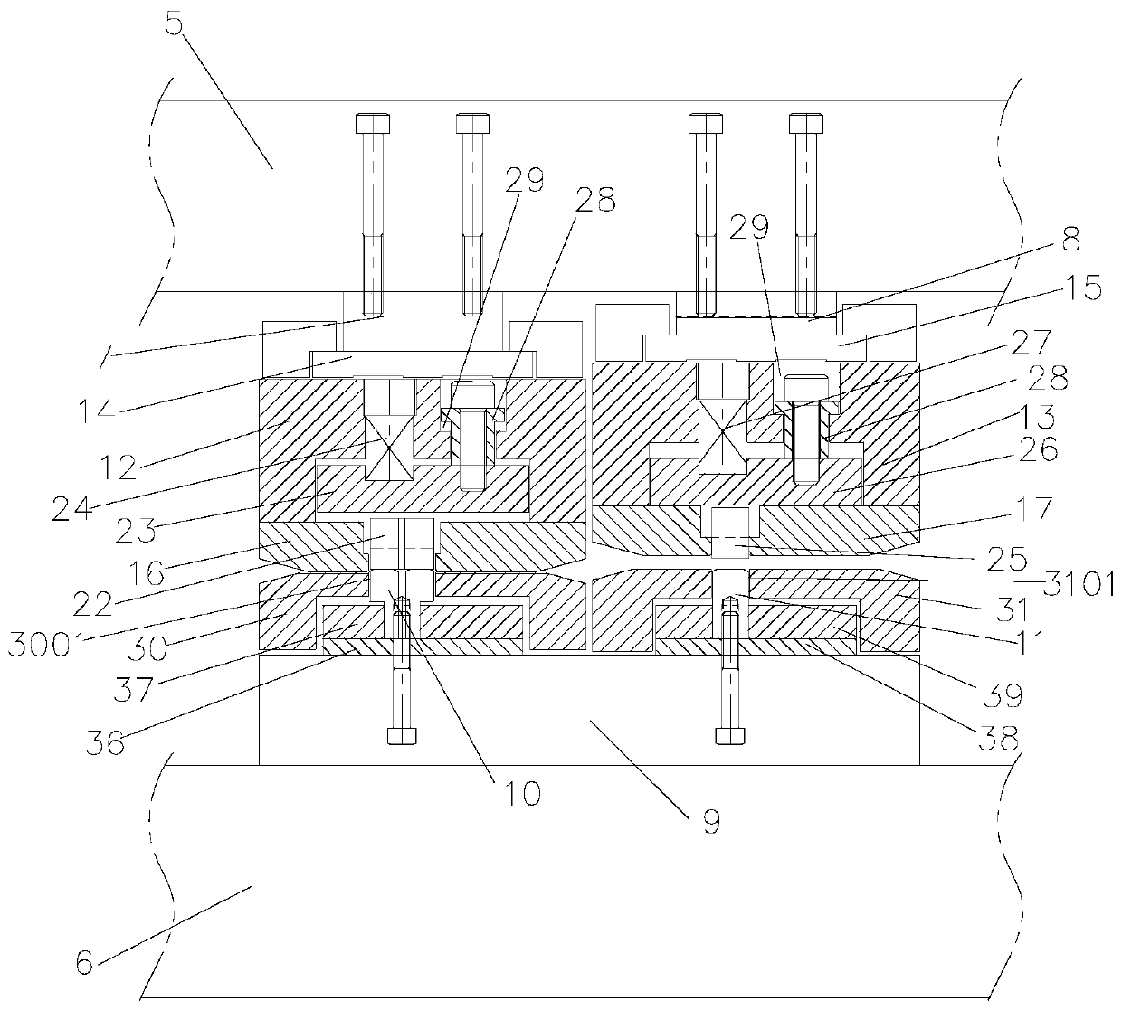
The invention discloses a twin-bridge fin structure and a twin-bridge fin machining die. The twin-bridge fin structure comprises at least one column of fin unit, a set of expansion rod installation holes are distributed on each column of fin units, a first bridge piece unit is arranged between every two adjacent expansion rod installation holes on each column of fin units. Each column of fin unitsis further provided with one set of second bridge piece unit. Each second bridge piece unit comprises long-bar-shaped bridge pieces which are arranged side by side and are consistent in length. The fin units are cut from the positions between the expansion rod installation holes and the second bridge piece units to form single fin structures, and therefore it is ensured that the fins cannot deform during cutting. Meanwhile, the twin-bridge fin machining die is further designed, forming of the first bridge piece units and the second bridge piece units can be switched online in time, the machining efficiency is high, and the twin-bridge fin structure and the twin-bridge fin machining die can be widely applied to the field of machining dies for forming two or more kinds of bridge piece unitson the same fin.

Description

technical field [0001] The invention relates to the technical field of air-conditioning fins, in particular to a double-bridge fin structure and a double-bridge fin processing mold. Background technique [0002] In order to facilitate the processing of the air conditioner fins, the structure of the bridges between the steps of the air conditioner fins is usually the same, and in order to obtain better heat dissipation performance, the distribution of the bridges on the air conditioner fins is mostly around the expansion rod hole, in a radial shape ,like figure 1 The structure is shown with two fins cut away. In this air-conditioning fin structure, when the air-conditioning fins are cut from the dividing line in the figure, the air-conditioning fins will be cut off on the bridge piece to cause deformation of the air-conditioning fins. Therefore, it is necessary to adjust the bridge structure on the air-conditioning fin so that the air-conditioning fin does not have a bridge...

Claims


Application Information

Patent Timeline
Patent Type & Authority Applications(China)
IPC IPC(8): F28F3/00B21D53/02B21D37/10
CPCB21D37/10B21D53/022F28F3/00
Inventor 储杰吴建军李文霞
Owner 黄山三佳谊华精密机械有限公司
Why Eureka
Try Eureka