Column-distributed ventilation heating system and method for high-pollution oil mist emission plant

A heating system, distributed technology, applied in the distributed ventilation and heating scheme along the column, and the distributed ventilation and heating system along the column, it can solve the problem of difficult to meet the thermal comfort requirements of tall factory buildings, difficult to control the internal area of ​​large space factory buildings, and the number of air supply outlets Issues such as the area can bear the load limit, to achieve the effect of improving the quality of the working environment, improving ventilation efficiency, and reducing energy consumption

Inactive Publication Date: 2020-02-14
TIANJIN UNIV
View PDF13 Cites 0 Cited by
  • Summary
  • Abstract
  • Description
  • Claims
  • Application Information

AI Technical Summary

Problems solved by technology

[0003] After investigation, the current situation of the domestic factory environment needs to be improved. Taking the machining workshop as an example, its processes usually include turning, milling, planing and grinding. The temperature requirements of tall factory buildings are usually regulated by high-volume mixed ventilation, and the messy airflow organization often leads to oil mist concentration limits that usually exceed worker health limits.
Researches at home and abroad have pointed out that the traditional displacement ventilation suitable for providing a cleaner space is usually installed near the enclosure structure. The area is also limited to the load that can be carried

Method used


Image

  • Column-distributed ventilation heating system and method for high-pollution oil mist emission plant
  • Column-distributed ventilation heating system and method for high-pollution oil mist emission plant
  • Column-distributed ventilation heating system and method for high-pollution oil mist emission plant

Examples


Embodiment 1

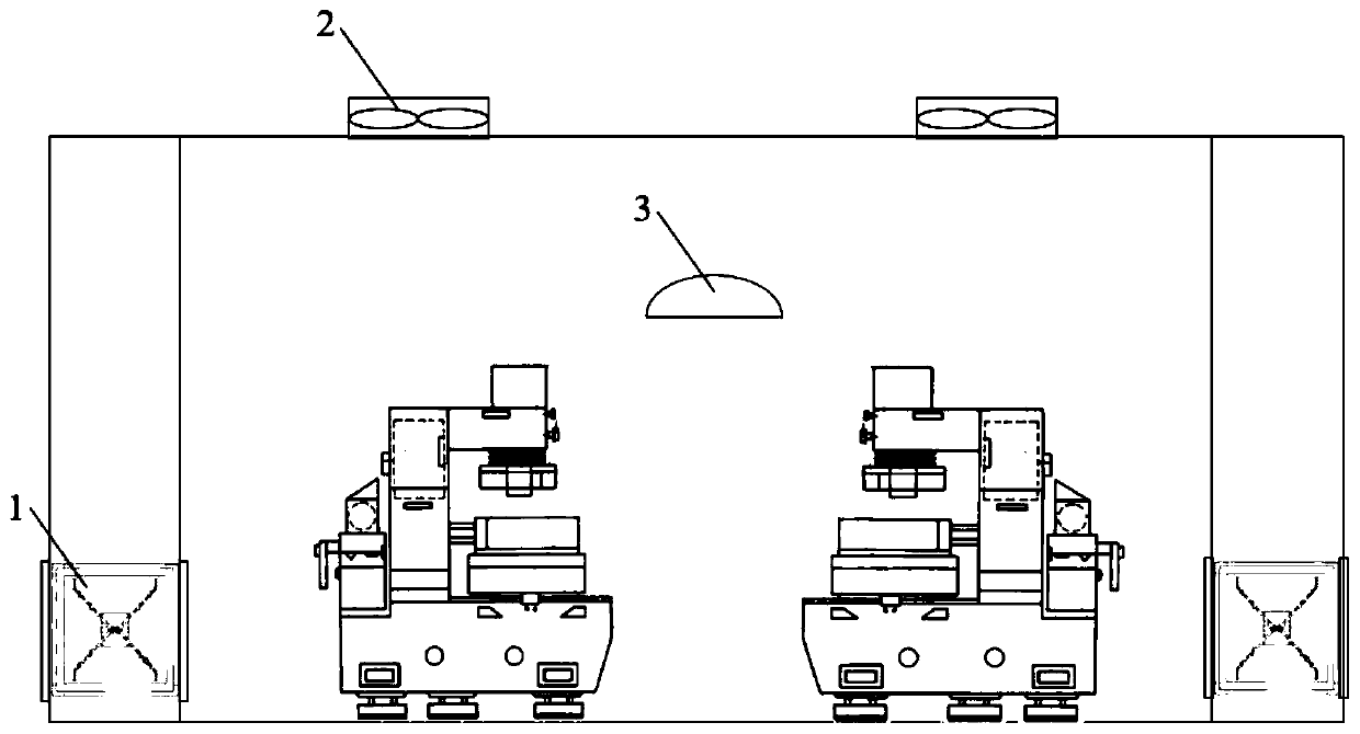
[0032] A ventilation and heating scheme suitable for high-pollution oil mist emission factory buildings in the present invention uses the original structural columns as air duct layout attachments inside the tall factory buildings to allow clean cold air to pass through the vents around the columns evenly When it flows into the factory building, it uses the principle of thermal buoyancy to drive the air up, and the fine aerodynamic properties of fine oil mist particles form a bottom-up displacement ventilation form that carries pollutants up and is discharged from the exhaust fan on the roof.

Embodiment 2

[0034] In order to verify the pollutant control effect of the column displacement ventilation provided by the present invention on the highly polluted oil mist emission factory building, a numerical model was established according to the actual factory conditions. 20m to 30m, evenly distributed in the factory building, the size of the air supply port is 1m×1.5m, the air supply speed is 1m / s, arranged around the column structure near the ground, the size of the roof exhaust device is 1m×1m, evenly arranged on the roof , the far-infrared auxiliary heater is above the production line, and the filament temperature is 400 °C. The ventilation effect of the present invention is judged by studying the average concentration of oil mist at the height of the breathing zone of the model.

[0035] In this verification, the turbulence model uses the RNG k-ε model based on Reynolds average, the difference format uses the second-order upwind style, and the SIMPLE algorithm is used to solve th...


PUM


Abstract

The invention discloses a column-distributed ventilation heating system and method for a high-pollution oil mist emission plant. The method comprises the steps that clean air lower than the room temperature is fed through air supply outlets formed in the periphery of a column structure of the high-pollution oil mist emission plant and below the height of a breathing area and passes through a working area in the high-pollution oil mist emission plant, personnel, process equipment and the like in the working area transfer heat to the clean air, the clean air carries oil mist generated in the working area to rise under the driving of thermal buoyancy and then is discharged from an exhaust outlet formed in the top of the high-pollution oil mist emission plant, and a ceiling infrared radiationheater arranged above a production line of the working area is started in an auxiliary mode when the fed air cannot meet the load requirement. Therefore, the ventilation efficiency can be effectivelyimproved, the energy consumption can be reduced, the oil mist concentration of the working area can be reduced, and the quality of the working environment can be improved.

Description

technical field [0001] The invention relates to the field of heating, ventilating and air conditioning, and relates to a column-along distributed ventilation and heating scheme suitable for high-pollution oil mist emission factory buildings, and in particular to a column-along distributed ventilation and heating system and method for high-pollution oil mist emission factory buildings. Background technique [0002] In recent years, with the urgent demand for green buildings, building indoor air quality and energy saving has become a research hotspot, but most of the related research focuses on civil buildings while industrial buildings are neglected. With the development of industrialization and the gradual emphasis on the working environment of workers, it is particularly important to propose a ventilation and heating scheme suitable for high-pollution industrial plants. [0003] After investigation, the current situation of the domestic factory environment needs to be impro...

Claims


Application Information

Patent Timeline
Patent Type & Authority Applications(China)
IPC IPC(8): F24F7/00F24F13/06F24D13/00
CPCF24D13/00F24F7/00F24F13/06
Inventor 魏冠琼赖达祎陈清焰
Owner TIANJIN UNIV
Why Eureka
Try Eureka