Air outlet for precise control of air supply direction and method for realizing different airflow organization

A technology of precise control and airflow organization, applied in the directions of airflow control elements, heating methods, space heating and ventilation, etc., it can solve the problems of fixed installation position, difficult adjustment of the air supply direction, and single form of air supply outlet, and achieves the best installation method. Flexible position, reducing the risk of wind blowing, the effect of uniform low-speed air supply

Active Publication Date: 2018-06-26
TIANJIN UNIV
View PDF6 Cites 0 Cited by
  • Summary
  • Abstract
  • Description
  • Claims
  • Application Information

AI Technical Summary

Problems solved by technology

However, there are also big problems in these single air supply outlet forms. For example, in some places with dense personnel or high mobility, since the form and position of the air supply outlet cannot be easily changed, the conventional air supply outlet form cannot meet the requirements of personnel on air volume and air supply. In addition, some industrial manufacturing plants, especially in certain narrow areas of closed spaces, have clear requirements and regulations on ventilation and air distribution, such as the air supply direction of the air conditioning system must meet a specific requirement, such as 60° downward, or it is required to take away pollutants by means of replacement air supply; secondly, for special personnel activity spaces, such as submarine cabins, spacecraft cabins, etc., the active personnel have a greater impact on the thermal environment and air quality inside the cabin. High demand, which requires that the air supply outlet at the end of the air conditioning system can not only achieve uniform low-speed air supply to reduce the feeling of blowing, but also meet the overall flow field inside the cabin to meet certain indicators, such as the speed range of 0.08-0.5m / s The flow field ratio is above 80%
At this time, ordinary air outlets on the market cannot meet the actual needs at all.
Therefore, due to the single form of the conventional air supply port, the installation position is fixed, and the air supply direction is not easy to adjust, it is difficult to meet the individual adjustment of personnel or the ventilation needs of special closed spaces.

Method used


Image

  • Air outlet for precise control of air supply direction and method for realizing different airflow organization
  • Air outlet for precise control of air supply direction and method for realizing different airflow organization
  • Air outlet for precise control of air supply direction and method for realizing different airflow organization

Examples


Embodiment Construction

[0029] The technical solution of the present invention will be further described in detail below in conjunction with the accompanying drawings and specific embodiments, and the described specific embodiments are only for explaining the present invention, and are not intended to limit the present invention.

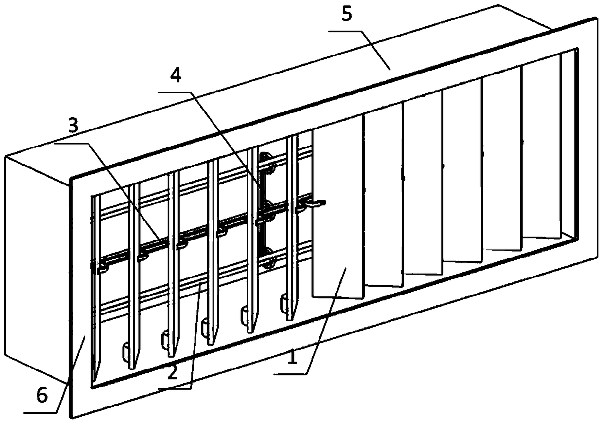
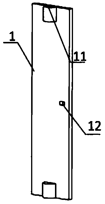
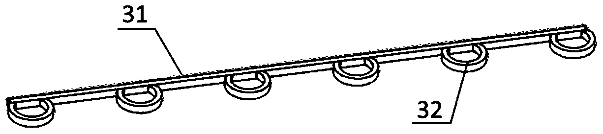
[0030] Such as Figure 1 to Figure 6 As shown, the present invention is an air supply port for precisely controlling the air supply direction, which includes a peripheral frame 5, and the peripheral frame 5 is provided with multiple rows of horizontally arranged first-stage blades 2 and multiple rows of vertically arranged secondary blades 1; all Both ends of the primary blade 2 and the secondary blade 1 are respectively connected in rotation with the peripheral frame 5; the rotation axes of all the secondary blades are on the same plane; The connecting rods 4 are connected to form a group of first-level louvers, and multiple rows of vertically arranged second-level blades...


PUM


Abstract

The invention discloses an air feeding port with the air feeding direction accurately-controlling function and a method for achieving different air flow structures of the air feeding port. The air feeding port structurally comprises an outer frame and multiple rows of horizontally-arranged first-level blades and multiple rows of vertically-arranged second-level blades are arranged in the outer frame; the two ends of each blade are rotationally connected with the outer frame; rotary shafts of the second-level blades are located on the same plane; the multiple rows of horizontally-arranged first-level blades are connected through a vertically connecting rod to form a set of first-level louvers and the multiple rows of vertically-arranged second-level blades are connected through horizontal connecting rods of the second-level blades respectively to form two sets of second-level louvers which are independent of each other; the first-level louvers and the second-level louvers are sequentially arranged in the air flow direction of the air feeding port; and an installation flange is arranged on the front face of the outer frame, the surface of the installation flange is provided with three scales respectively, and the scales are used for indicating the rotation angles of the first-level louvers and the second-level louvers. The air feeding port can be used in various sealed spaces, the optimal air flow structure manner can be created, and personnel can freely adjust the air feeding direction and the air flow.

Description

technical field [0001] The invention relates to the technical field of air conditioning, in particular to an air supply outlet for air volume distribution in a closed space where the air supply direction of an air conditioning system can be precisely controlled. Background technique [0002] With the continuous advancement of technology, air-conditioning systems are widely used in civil buildings and industrial plants. The thermal comfort of personnel and the needs of industrial manufacturing. The form of the air supply outlet at the end of the air conditioning system is an important factor affecting the airflow organization. At present, the commonly used forms of air supply outlets are louver air outlets, grille air outlets, diffusers and orifice air supply outlets, etc. According to the characteristics and requirements of space objects and reasonable selection of air outlet forms and installation positions, the required air flow organization form can be realized. However...

Claims


Application Information

Patent Timeline
Patent Type & Authority Patents(China)
IPC IPC(8): F24F13/15
CPCF24F1/0011F24F13/15
Inventor 刘俊杰代申朱学良李佳钰孙贺江
Owner TIANJIN UNIV
Why Eureka
Try Eureka