Novel low-pressure air combustion supporting torch combustor

A torch combustion and air technology, which is applied in the direction of gas fuel burners, burners, combustion methods, etc., can solve safety risks such as big explosions, steam combustion-supporting torches are not suitable for use, and block the torch outlet, etc., to reduce equipment operation cost, save low-pressure air volume, increase mixing effect

Inactive Publication Date: 2020-02-14
BEIJING HANGHUA ENERGY SAVING ENVIRONMENTAL PROTECTION TECH CO LTD
View PDF7 Cites 4 Cited by
  • Summary
  • Abstract
  • Description
  • Claims
  • Application Information

AI Technical Summary

Problems solved by technology

The structure proposed by the patent CN 206755166 U is an internal mixing structure, which has great safety risks such as explosion, and is easy to freeze to block the outlet of the torch in cold regions, and the technology of the steam-assisted combustion type torch burner in the prior art is very mature. For example, patents such as CN201120287259 and CN201520563616 all adopt the principle of steam combustion-assisted smoke suppression, and the smoke suppression effect is very obvious
However, due to the limited environment of the torch site, the steam-assisted combustion torch is not suitable for use in environments such as water shortages or cold weather.

Method used


Image

  • Novel low-pressure air combustion supporting torch combustor
  • Novel low-pressure air combustion supporting torch combustor
  • Novel low-pressure air combustion supporting torch combustor

Examples


Embodiment 1

[0052] The invention relates to a novel low-pressure air combustion-supporting torch burner, which has the advantages of good smoke elimination effect, preventing burning loss and smoldering, and the like. Now with examples to illustrate as follows.

[0053] This burner is used in an elevated flare project, and the flare gas is oilfield associated gas. The setting of the torch burner is as follows: the air cylinder adopts DN900, the torch head cylinder adopts DN300, the gas distributor is equipped with 8 arms, and each arm is punched in 4 rows, and the holes in each row are aligned (non-staggered) , 12 holes in each column, 48 holes in total. The distance between the fin plate and the upper semicircle of the support arm is 10mm. Specifically, the distance from the intersection of the upper semicircle and the side straight line is 10mm. The distance between the fin plate and the arm is 3 holes shorter than the length of the support arm, that is, 8 holes are reserved as the fla...

Embodiment 2

[0056] The invention relates to a novel low-pressure air combustion-supporting torch burner, which has the advantages of good smoke elimination effect, high utilization rate of combustion-supporting medium, and saving public works consumption. Now with examples to illustrate as follows.

[0057] In the laboratory, the burner is compared with the jacket structure of the straight-through gas distributor. In this test, propylene is used as the main flare gas component. The amount of low-pressure air consumed when achieving the same smoke elimination effect (zero-level Ringelmann blackness), the burner with the structure of the invention can save 10% of air consumption.


PUM


Abstract

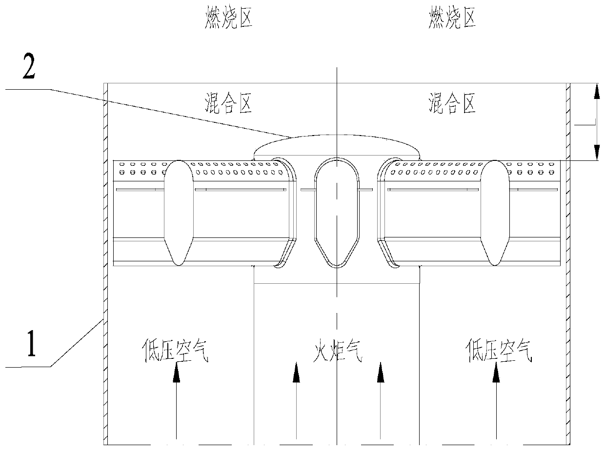
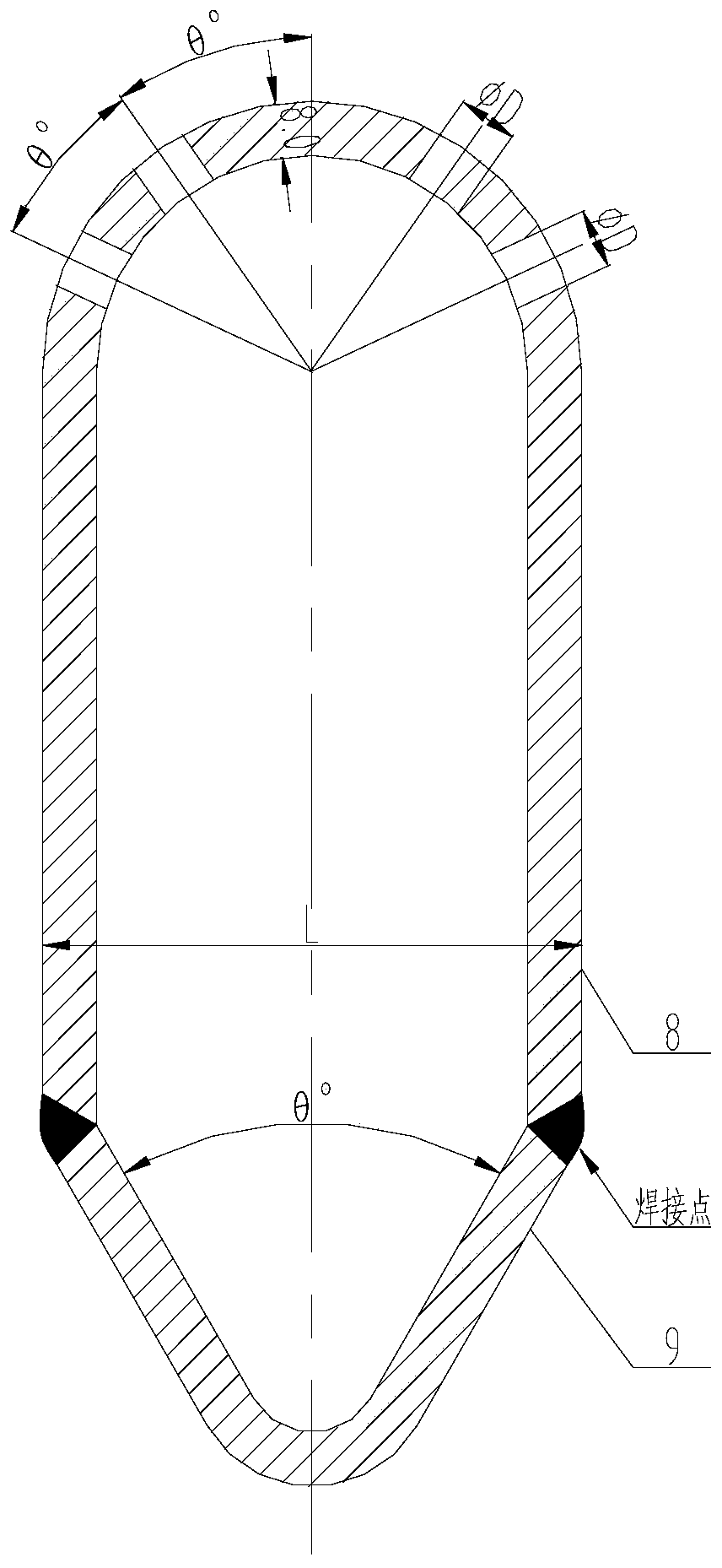
The invention relates to a novel low-pressure air combustion supporting torch combustor which is jacket structure form that a torch gas distributor is arranged in a barrel. Through design of the direction, the number, the distribution and the hole diameter of spraying holes in the torch gas distributor, torch gas is sprayed towards low-pressure air with a certain angle in space, and in other words, direct current cross mixing is conducted; and through the mixing manner, the torch gas and the low-pressure air can be sufficiently mixed, and the effect of smokeless combustion is achieved. To prevent flame blowoff, a fin plate structure is arranged at the proper position of the torch gas distributor, and fin plates are provided with a plurality of proper holes. Through design of the torch combustor structure, the torch gas and the low-pressure air are subjected to rotational flow mixing, and the purpose of removing black smoke is achieved. By utilization of reasonable control over the combustion area position, the purpose of reducing the combustor surface temperature is achieved, and combustor burning losses are prevented.

Description

technical field [0001] The invention belongs to a novel low-pressure air combustion-supporting torch burner, and in particular relates to the structure of the low-pressure air combustion-supporting torch burner. Background technique [0002] Industrial torches are widely used in petrochemical, coal chemical, refining, coking, fine chemical and other energy and chemical enterprises. They are used to release various flammable and explosive gases in the chemical industry when processing equipment is on / off, under normal working conditions and emergencies. Provide the last barrier of safety. At present, the emission of heavy hydrocarbons in the chemical industry requires that the total amount of combustion products and residues, as well as the emission rate and ground concentration are within the allowable range of the regulations; flammable and harmful substances should be burned and decomposed into harmless and non-combustible substances as fully as possible. Produces black s...

Claims


Application Information

Patent Timeline
Patent Type & Authority Applications(China)
IPC IPC(8): F23G7/08F23D14/62F23D14/70F23L7/00
CPCF23D14/62F23D14/70F23G7/08F23G2209/14F23L7/005
Inventor 韩宗捷曹毅庞宗占吴红英李北辰李泓达马晓蓉
Owner BEIJING HANGHUA ENERGY SAVING ENVIRONMENTAL PROTECTION TECH CO LTD
Why Eureka
Try Eureka