Eureka AIR delivers breakthrough ideas for toughest innovation challenges, trusted by R&D personnel around the world.

Urea solution supply system adopting double pneumatic diaphragm pumps

A pneumatic diaphragm pump and solution supply technology, applied in exhaust treatment, exhaust devices, engine components, etc., can solve the problems of narrow flow adjustment range, complex control system, poor reliability, etc., to achieve a wide flow adjustment range and reduce complexity. degree, the effect of preventing clogging

Active Publication Date: 2020-02-14
HUAZHONG UNIV OF SCI & TECH
View PDF9 Cites 1 Cited by
  • Summary
  • Abstract
  • Description
  • Claims
  • Application Information

AI Technical Summary

Problems solved by technology

However, the existing urea solution supply system has disadvantages such as poor reliability, low efficiency, complex control system, and narrow flow adjustment range.

Method used


Image

  • Urea solution supply system adopting double pneumatic diaphragm pumps

Examples


Embodiment Construction

[0021] In order to make the object, technical solution and advantages of the present invention clearer, the present invention will be further described in detail below in conjunction with the accompanying drawings and embodiments. It should be understood that the specific embodiments described here are only used to explain the present invention, not to limit the present invention. In addition, the technical features involved in the various embodiments of the present invention described below can be combined with each other as long as they do not constitute a conflict with each other.

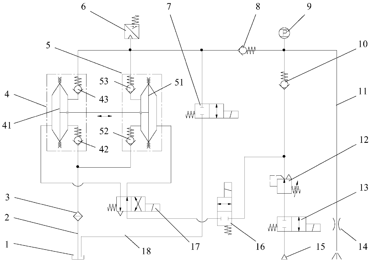
[0022] Such as figure 1 As shown, the embodiment of the present invention provides a urea solution supply system using a pneumatic double-diaphragm pump, which includes a first pneumatic diaphragm pump 4, a second pneumatic diaphragm pump 5, a urea tank 1, an air source 15 and a urea nozzle 14 ,in:

[0023] After the liquid inlet ends of the first pneumatic diaphragm pump 4 and the second pneu...


PUM


Abstract

The invention belongs to the field of diesel engine tail gas after-treatment, and particularly discloses a urea solution supply system adopting double pneumatic diaphragm pumps. The system comprises the first pneumatic diaphragm pump, the second pneumatic diaphragm pump, a urea box, an air source and a urea nozzle. The liquid inflow ends of the first pneumatic diaphragm pump and the second pneumatic diaphragm pump communicate and then are connected with the urea box through a liquid inflow pipeline, the liquid outflow ends of the first pneumatic diaphragm pump and the second pneumatic diaphragm pump communicate and then are divided into two paths, one path is connected with the urea box through a return pipeline, the other path is connected with the urea nozzle through a spraying pipeline,the air source is divided into two paths, one path is connected with the air inflow ends of the first pneumatic diaphragm pump and the second pneumatic diaphragm pump through a two-position four-wayelectromagnetic valve, the other path is connected with the urea nozzle, and a urea solution is purged. Suction of one path of pneumatic diaphragm pump and pressing-out of the other path of pneumaticdiaphragm pump always exist in one working cycle, the flow pulsation rate of the system is effectively reduced, and the flow stability and the metering precision of the urea solution supply system areimproved.

Description

technical field [0001] The invention belongs to the field of post-treatment of diesel engine exhaust, and more specifically relates to a urea solution supply system using a pneumatic double-diaphragm pump. Background technique [0002] The exhaust gas emitted by diesel engines after combustion contains a large amount of particulate matter and NOx, which poses a great threat to air quality. However, the current in-engine purification technology cannot fully meet the increasingly stringent emission standards, so the installation of exhaust after-treatment devices on diesel engines has a great application prospect. [0003] At present, the main technical methods for reducing NOx emissions from diesel vehicles in the world are: Exhaust Gas Recirculation (EGR), Selective Catalytic Reduction (SCR), NOx Adsorption Converter (LNT), etc. However, SCR technology has high NOx conversion efficiency, simple engine control, good fuel economy, and relatively easy technology upgrades. It h...

Claims


Application Information

Patent Timeline
Patent Type & Authority Applications(China)
IPC IPC(8): F01N3/20
CPCF01N3/2066F01N2570/14F01N2610/02F01N2610/14F01N2610/1426F01N2610/1433F01N2610/148F01N2610/1493
Inventor 杨曙东潘希伟史有程
Owner HUAZHONG UNIV OF SCI & TECH
Why Eureka
Eureka Blog
Learn More