
Cutting inserts based on graphene sensors

A technology of cutting blades and sensors, applied to lathe tools, turning equipment, accessories of tool holders, etc., can solve the problems of narrow application range and susceptibility to interference

Active Publication Date: 2021-04-16
北京石墨烯技术研究院有限公司
View PDF9 Cites 0 Cited by
  • Summary
  • Abstract
  • Description
  • Claims
  • Application Information

AI Technical Summary

Problems solved by technology

[0004] Based on this, it is necessary to provide a graphene sensor-based cutting blade for the existing tool wear monitoring methods that have a narrow scope of application and are susceptible to interference.

Method used


Image

  • Cutting inserts based on graphene sensors
  • Cutting inserts based on graphene sensors
  • Cutting inserts based on graphene sensors

Examples


Embodiment Construction

[0056] In order to make the above purpose, features and advantages of the present application more obvious and understandable, the specific implementation manners of the present application will be described in detail below in conjunction with the accompanying drawings. In the following description, numerous specific details are set forth in order to provide a thorough understanding of the application. However, the present application can be implemented in many other ways different from those described here, and those skilled in the art can make similar improvements without departing from the connotation of the present application. Therefore, the present application is not limited by the specific implementation disclosed below.

[0057] It should be noted that when an element is referred to as being “fixed” to another element, it can be directly on the other element or there can also be an intervening element. When an element is referred to as being "connected to" another elem...


PUM


Abstract

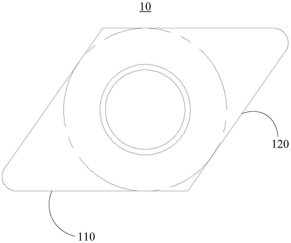
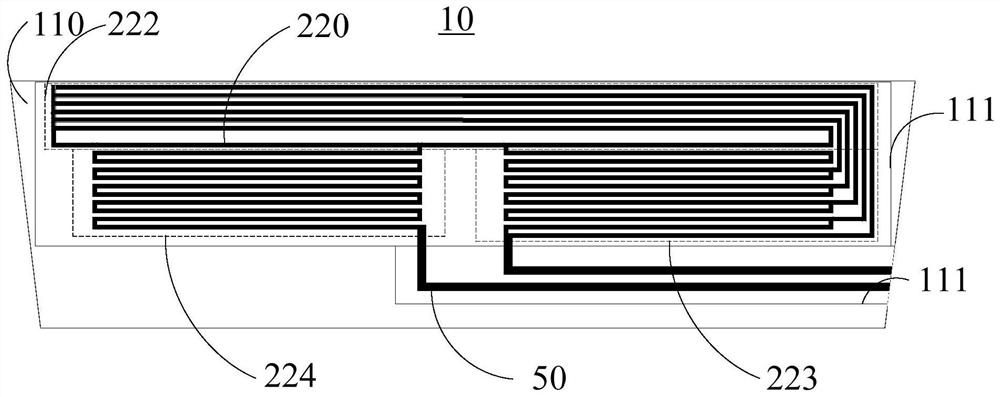
The present application relates to a cutting blade based on a graphene sensor, including a cutting blade, a graphene sensor and a detection circuit. The cutting insert includes a main flank and a mounting flank. The graphene sensor includes two electrodes and a resistance grid connected in series between the two electrodes, wherein the two electrodes are arranged on the side of the installation, the resistance grid is arranged on the main flank, and the resistance of the resistance grid changes when the cutting blade is worn. The detection circuit is electrically connected to the two electrodes respectively, and is used to detect the current change at both ends of the resistance grid, calculate the resistance value change of the resistance grid according to the current change, and determine the wear degree of the cutting blade according to the resistance value change of the resistance grid. The graphene-based cutting insert can detect the wear of the cutting edge in different degrees, and can realize the real-time detection of the wear state of the cutting edge during the cutting process without being disturbed by the grid voltage or electromagnetic noise.

Description

technical field [0001] The present application relates to the technical field of tool wear monitoring, in particular to a cutting blade based on a graphene sensor. Background technique [0002] During workpiece processing, there is vibration between the cutting tool and the workpiece to be processed, and the extrusion and friction between the two will generate a lot of heat, resulting in wear of the cutting blade. Therefore, monitoring the wear of cutting inserts can ensure the quality and performance of workpieces, and at the same time provide reference data for process improvement, cutting insert design and cutting mechanism. [0003] Existing tool wear monitoring methods mainly use spindle torque monitoring, machining sound monitoring, and optical wear offset monitoring. However, the above tool wear monitoring methods are only suitable for rough machining and are easily disturbed by grid voltage and electromagnetic noise. Contents of the invention [0004] Based on th...

Claims


Application Information

Patent Timeline
Patent Type & Authority Patents(China)
IPC IPC(8): B23Q17/09B23B27/00B23B25/06
CPCB23B25/06B23B27/00B23Q17/0957
Inventor 李学瑞李文博李炯利王旭东
Owner 北京石墨烯技术研究院有限公司
Learn More