Reagent storage equipment
A technology for reagent storage and equipment, which is applied in the field of reagent storage equipment, can solve problems such as the inconvenience of taking reagents, and achieve the effect of improving operation convenience and efficiency
- Summary
- Abstract
- Description
- Claims
- Application Information
AI Technical Summary
Problems solved by technology
Method used
Image
Examples
Embodiment 1
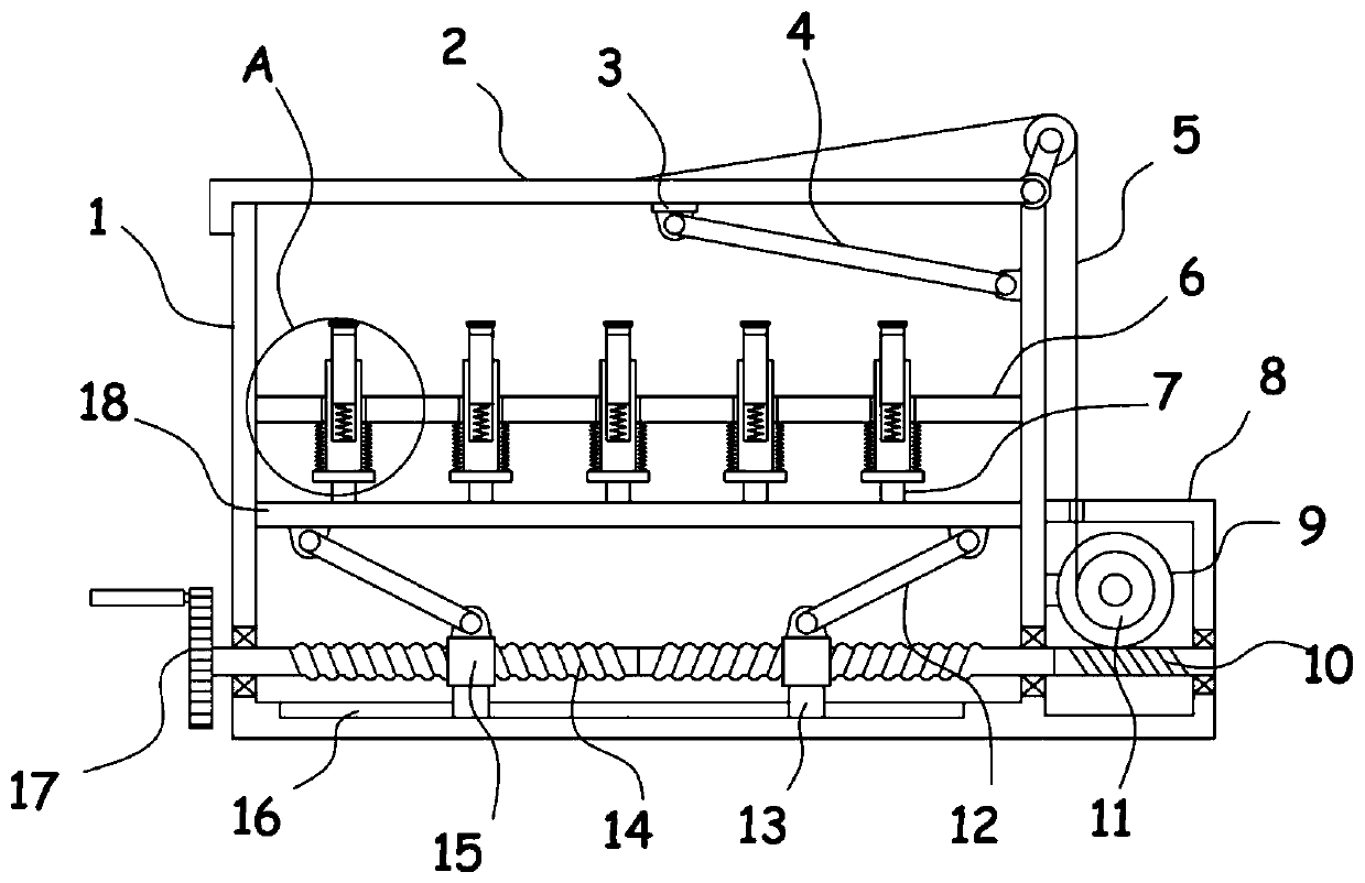
[0023] refer to figure 1 , figure 2 and image 3 As shown, a reagent storage device includes a box body 1, the top of the box body 1 is rotatably installed with a cover plate 2, a fixed plate 6 is fixed horizontally inside the box body 1, and several sliding plates are provided on the fixed plate 6 for carrying The support mechanism of the test tube 19, the box body 1 is driven and connected with a push mechanism for vertical height adjustment of the support mechanism through the lifting adjustment mechanism, the side wall of the box body 1 is fixed with a transmission box 8, and the inside of the transmission box 8 An opening and closing mechanism for driving the cover plate 2 to rotate is provided.
[0024] The support mechanism provided in this device is used to support and place the test tube 19, so that the test tube 19 is stored and stored inside the box body 1, wherein the support mechanism includes a test tube holder 20 that slides through the fixed plate 6, and the...
Embodiment 2
[0029] On the basis of Embodiment 1, in addition, specifically, the lifting adjustment mechanism includes two threaded rods 14 coaxially fixed in opposite directions. The threaded rods 14 are threaded with a threaded block 15, and the threaded block 15 and Support rods 12 are hinged between the lifting plates 18, and a hand crank 17 outside the casing 1 is fixed on the threaded rods 14.
[0030] The reagent is stored in the test tube 19, and the test tube 19 is placed inside the cabinet 1 to realize the storage of the reagent. When the test tube 19 is taken, the threaded rod 14 is driven to rotate by shaking the handle 17, and the two threaded sleeves on the threaded rod 14 The connected threaded blocks 15 move towards each other, and the threaded blocks 15 push the lifting plate 18 to move vertically upwards through the support rod 12. At this time, the lifting plate 18 drives the top block 7 to push the bottom plate 23 upwards to drive the test tube holder 20 to move up toget...
PUM
 Abstract
Description
Claims
Application Information
 - R&D
- Intellectual Property
- Life Sciences
- Materials
- Tech Scout
- Unparalleled Data Quality
- Higher Quality Content
- 60% Fewer Hallucinations
Browse by: Latest US Patents, China's latest patents, Technical Efficacy Thesaurus, Application Domain, Technology Topic, Popular Technical Reports.
© 2025 PatSnap. All rights reserved.Legal|Privacy policy|Modern Slavery Act Transparency Statement|Sitemap|About US| Contact US: help@patsnap.com


