
Denitration-demercuration integrated device and method used in circulating fluidized bed desulfurization of sintering flue gas

A technology of circulating fluidized bed and sintering flue gas, applied in chemical instruments and methods, gas treatment, separation methods, etc., can solve the problems of difficult control of mercury, mercury pollution, low solubility, etc., to promote the formation of SO3, reduce Pollution, wide-ranging effects

Active Publication Date: 2020-02-14
ANHUI UNIVERSITY OF TECHNOLOGY
View PDF8 Cites 7 Cited by
  • Summary
  • Abstract
  • Description
  • Claims
  • Application Information

AI Technical Summary

Problems solved by technology

The form of mercury in flue gas: elemental mercury (Hg 0 ), monovalent mercury (Hg + ) and divalent gaseous mercury (Hg 2+ ), the mercury present in particulate form in flue gas (Hg + ) can be partially removed by dust removal equipment such as bag filter or classic dust collector, divalent mercury (Hg 2+ ) is relatively stable, easily soluble in water, and can be removed by adsorption by fly ash in flue gas or by desulfurization equipment, while elemental mercury (Hg 0 ) has a low solubility in water and can exist relatively stably in the atmosphere, while mercury existing in the gas phase is more difficult to control, which in turn will form global mercury pollution

Method used


Image

  • Denitration-demercuration integrated device and method used in circulating fluidized bed desulfurization of sintering flue gas
  • Denitration-demercuration integrated device and method used in circulating fluidized bed desulfurization of sintering flue gas
  • Denitration-demercuration integrated device and method used in circulating fluidized bed desulfurization of sintering flue gas

Examples


Embodiment 1

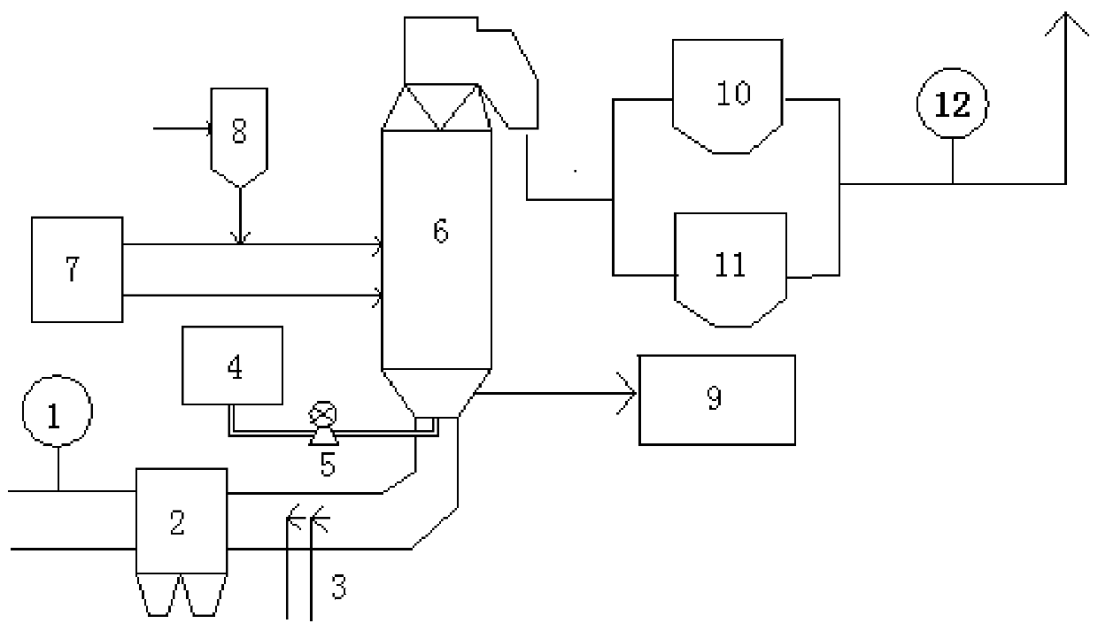
[0054] Example 1: The flue gas volume of sintering flue gas is 1 million Nm 3 / h, where SO 2 The content is 650~800mg / Nm 3 , NO X The content is 200~280mg / Nm 3 , the oxygen content is 13-16%, and the water content is 5-7%. When the flue gas enters the pipeline through the electrostatic precipitator, the prepared component A of the denitrification oxidant is sprayed into the flue with a high-pressure spray gun, and the formed mist water vapor fully contacts with the flue gas, and quickly oxidizes NO to NO 2 , SO 2 in Fe 3+ Catalyzed by ions into SO 3 , consume about 276-387Kg / h of denitrification oxidizer A component. At the same time, the lime is added into the pipeline where the industrial water tank is located through the digestion tank, and the B component of the denitration reduction absorbent in the denitration reduction absorbent tank is sprayed into the bottom of the CFB reactor through the denitration pump, and then enters the CFB reactor to participate in the r...

Embodiment 2

[0055] Example 2: The flue gas volume of sintering flue gas is about 1.3 million Nm 3 / h, where SO 2 The content is 680~850mg / Nm 3 , NO X The content is 210~250mg / Nm 3 , the oxygen content is about 14-16%, and the water content is about 8-10%. When the flue gas enters the pipeline through the electrostatic precipitator, the prepared component A of the denitrification oxidant is sprayed into the flue with a high-pressure spray gun, and fully contacts with the flue gas to quickly oxidize NO to NO 2 , SO 2 in Fe 3+ Catalyzed by ions into SO 3 , about 364.7-432.9Kg / h of component A of the denitrification oxidant is consumed. At the same time, the lime is added into the pipeline where the industrial water tank is located through the digestion tank, and the B component of the denitration reduction absorbent in the denitration reduction absorbent tank is sprayed into the bottom of the CFB reactor through the denitration pump, and then enters the CFB reactor to participate in t...

Embodiment 3

[0056] Example 3: The flue gas volume of sintering flue gas is about 1.6 million Nm 3 / h, where SO 2 The content is 800~1000mg / Nm 3 , NO X The content is 250~280mg / Nm 3 , the oxygen content is about 15-16%, and the water content is about 10-11%. When the flue gas enters the pipeline through the electrostatic precipitator, the prepared component A of the denitrification oxidant is sprayed into the flue with a high-pressure spray gun, and fully contacts with the flue gas to quickly oxidize NO to NO 2 , SO 2 in Fe 3+ Catalyzed by ions into SO 3, about 523.2-583.2Kg / h of component A of the denitrification oxidant is consumed. At the same time, the lime is added into the pipeline where the industrial water tank is located through the digestion tank, and the B component of the denitration reduction absorbent in the denitration reduction absorbent tank is sprayed into the bottom of the CFB reactor through the denitration pump, and then enters the CFB reactor to participate in ...


PUM


Abstract

The invention discloses a denitration-demercuration integrated device and method used in circulating fluidized bed desulfurization of sintering flue gas, belonging to the technical field of desulfurization and denitration of sintering flue gas. The device comprises a CFB reactor, an industrial water tank, a digestion tank, a denitration reduction absorbent tank, a cloth bag dust removal system, aflue gas monitoring system and an electrostatic dust removal system. The method comprises the following steps that firstly, a denitration oxidant component A of is sprayed into a flue located betweenan electrostatic dust collector and a CFB reactor, and can rapidly oxidize a part of NO in flue gas into a high-valence-state multi-nitrogen-oxide mixture easy to absorb by water vapor, and then the high-valence-state multi-nitrogen-oxide mixture enters the CFB reactor; and a denitration reduction absorbent component B is sprayed into the CFB reactor, lime is sprayed into the CFB reactor, and desulfurized and denitrated flue gas undergoes dust removal and is then discharged after being detected by the flue gas monitoring system. The method disclosed by the invention is simple, environment-friendly, circular and pollution-free, and has low operation cost and remarkable economic and environmental benefits.

Description

Technical field: [0001] The invention belongs to the technical field of desulfurization and denitrification of sintering flue gas, and in particular relates to an integrated device and method for denitrification and demercuration in desulfurization of sintering flue gas circulating fluidized bed. Background technique: [0002] Sintering flue gas is the main source of air pollutants emitted by iron and steel enterprises, mainly including sulfur dioxide, nitrogen oxides, particulate matter, dioxins, heavy metals and other pollutants, among which sulfur dioxide, nitrogen oxides and trace toxic Pollution control and emission reduction of metal element mercury. With the introduction of the ecological civilization construction and green development policy of the Fifth Plenary Session of the Thirteenth Central Committee of the Communist Party of China, the iron and steel industry's original desulfurization-based single pollutant treatment has been transformed into a multi-pollutant...

Claims


Application Information

Patent Timeline
IPC IPC(8): B01D53/75B01D53/86B01D53/78B01D53/56B01D53/50B01D46/02B01D46/44
CPCB01D53/75B01D53/8696B01D53/8628B01D53/56B01D53/502B01D53/504B01D53/78B01D46/023B01D46/44B01D2258/0283B01D2257/404B01D2251/2067B01D2251/21B01D2251/902B01D2251/404B01D2251/608
Inventor 潘梦雅张千峰李玉娇陆伟星
Owner ANHUI UNIVERSITY OF TECHNOLOGY
Learn More