
Multi-frequency microstrip slot antenna with earth plate loaded with slip-ring resonator slots

A technology of split ring resonator and microstrip slot, which is applied in the direction of slot antenna, antenna grounding switch structure connection, antenna, etc., can solve the problems of single operating frequency point of microstrip antenna and low reliability of intelligent wireless mobile communication equipment, and achieve Achieve miniaturization, reduce complexity, and improve reliability

Active Publication Date: 2020-02-11
榆林浩林源网络科技有限公司
View PDF6 Cites 5 Cited by
  • Summary
  • Abstract
  • Description
  • Claims
  • Application Information

AI Technical Summary

Problems solved by technology

However, the existing microstrip antenna has a single operating frequency point, and the number of integrated antennas in the smart wireless communication device is large, resulting in low reliability of the smart wireless mobile communication device

Method used


Image

  • Multi-frequency microstrip slot antenna with earth plate loaded with slip-ring resonator slots
  • Multi-frequency microstrip slot antenna with earth plate loaded with slip-ring resonator slots
  • Multi-frequency microstrip slot antenna with earth plate loaded with slip-ring resonator slots

Examples


Embodiment Construction

[0026] In order to make the purpose, technical solutions and advantages of the embodiments of the present invention clearer, the technical solutions of the present invention will be clearly and completely described below in conjunction with the accompanying drawings. Obviously, the described embodiments are part of the embodiments of the present invention, not all of them. the embodiment. Based on the embodiments of the present invention, all other embodiments obtained by persons of ordinary skill in the art without making creative efforts belong to the protection scope of the present invention.

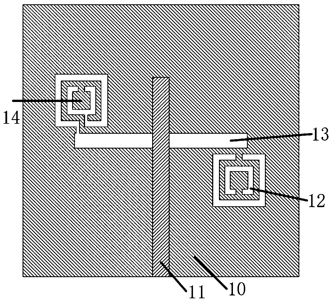
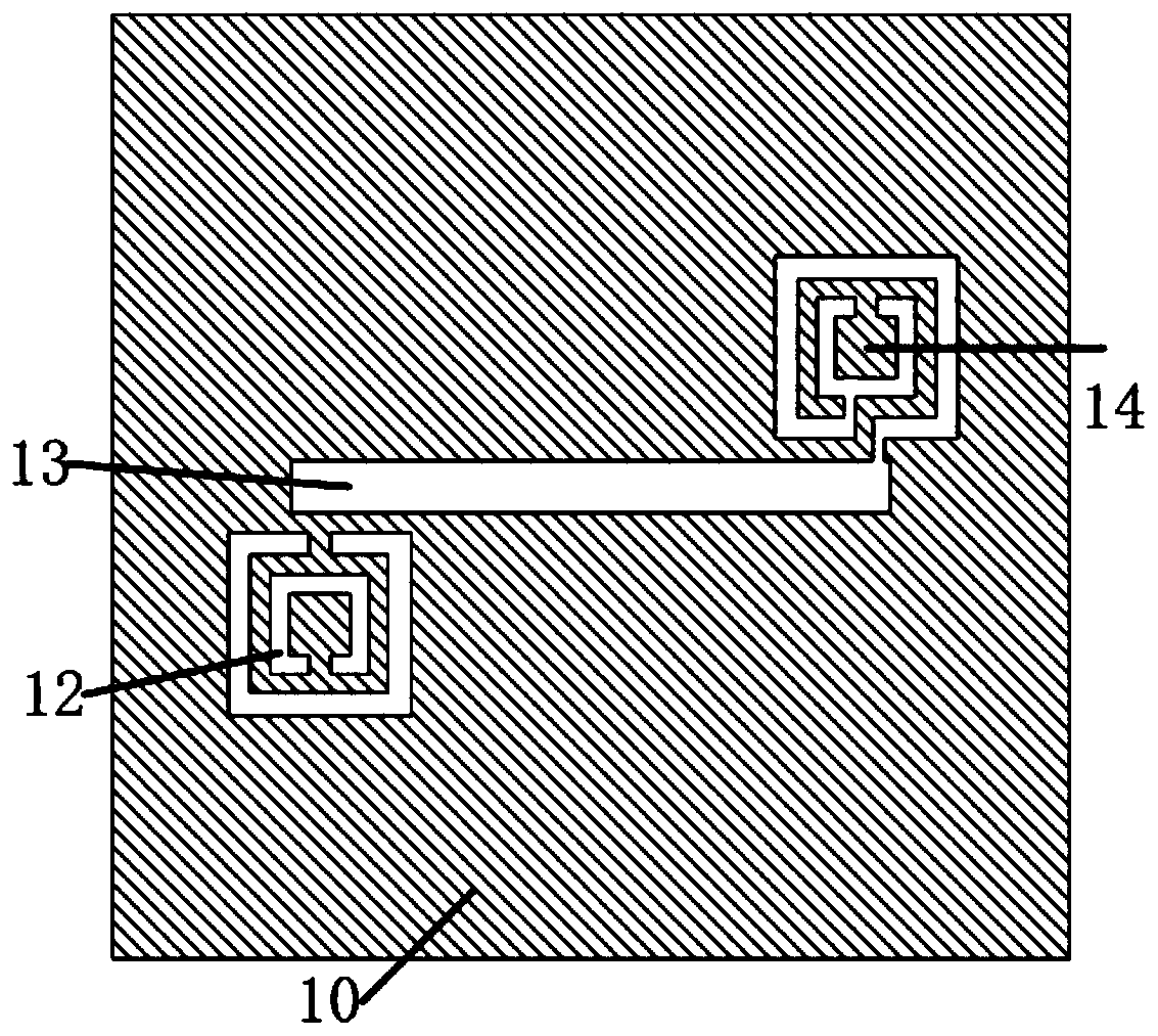
[0027] combine figure 1 , figure 2 with image 3 As shown, as a specific embodiment of the present invention, a multi-frequency microstrip slot antenna in which the ground plate loads the gap of the split ring resonator includes a metal ground plate 10, the upper end surface of the metal ground plate 10 is provided with a dielectric substrate 15, The size of the metal ground plat...


PUM


Abstract

The invention discloses a multi-frequency microstrip slot antenna with an earth plate loaded with slip-ring resonator slots. The multi-frequency microstrip slot antenna includes a metal earth plate. Adielectric substrate is disposed on the upper end surface of the metal earth plate. A rectangular microstrip signal line is disposed on the upper end surface of the dielectric substrate. The narrow side of the rectangular microstrip signal line coincides with one side of the dielectric substrate. The lower end surface of the metal earth plate is provided with a rectangular radiation slot. The long side of the rectangular radiation slot is orthogonal to the long side of the rectangular microstrip signal line. The two narrow sides of the rectangular radiation slot are symmetrical with respect to a connecting line of the centers of the two narrow sides of the rectangular microstrip signal line. The lower end surface of the metal earth plate is also provided with a first split-ring resonatorslot and a second split-ring resonanor slot. The first split-ring resonator slot is located on a side of one end of the rectangular radiation slot. The second split-ring resonator slot is located on the other side of the other end of the rectangular radiation slot. The multi-frequency microstrip slot antenna of the present invention can opearate at three frequency points simultaneously, can be applied to wireless mobile communication systems, especially mobile communication equipment, effectively reduces the complexity of the equipment and improve the reliability of the equipment.

Description

technical field [0001] The invention belongs to the technical field of microstrip antennas, in particular to a multi-frequency microstrip slot antenna in which a ground plate loads a gap of a split ring resonator. Background technique [0002] While the rapid development of information technology has brought great convenience to human life, it is also changing people's traditional production and lifestyle. Especially after the arrival of the fifth-generation wireless communication technology characterized by high speed, low latency and large capacity, all things in society can be connected to the Internet, and can be intelligent or remotely controlled to form an Internet of Things system. Since then, human society has entered the era of intelligence and wisdom. The Internet of Things is to connect any item with the Internet through information sensing devices such as radio frequency identification (RFID), infrared sensors, wireless sensing technology, laser scanners, and gl...

Claims


Application Information

Patent Timeline
IPC IPC(8): H01Q13/10H01Q1/38H01Q1/48H01Q1/50H01Q5/10H01Q5/28H01Q5/307
CPCH01Q13/106H01Q1/38H01Q1/48H01Q1/50H01Q5/10H01Q5/28H01Q5/307
Inventor 李海雄张雅琼崔娟娟冯治东
Owner 榆林浩林源网络科技有限公司
Learn More