Oral cavity scanning instrument

An oral scanner and the technology of the scanning unit, applied in the field of oral scanners, can solve the problems of stimulating saliva secretion, fatigue, and a large increase in saliva secretion, and achieve high-quality scanning, relieve fatigue, and reduce saliva secretion.

Pending Publication Date: 2020-02-11
李勇
View PDF1 Cites 1 Cited by
  • Summary
  • Abstract
  • Description
  • Claims
  • Application Information

AI Technical Summary

Problems solved by technology

[0003] That is to say, the scanner host and dental speculum head of the above structure are mobile, and the doctor controls the movement of the dental speculum head on the teeth by adjusting the angle of the scanner host. It needs to be controlled by human experience, and it is difficult to perform a full scan of the inside of the oral cavity, that is, the moving speed of the dental speculum head and its length in the oral cavity directly affect the scanning effect of the teeth
[0004] In addition, existing oral scanners generally do not have an oral support device. During the scanning process of the dental speculum head sliding on the teeth, it is difficult for the patient to keep the oral cavity in an active open state. After the patient keeps the oral cavity open for a period of time, the Muscles are prone to spasm or fatigue. Proper occlusal training is required to relieve the above symptoms. The oral scan can only be continued after the above symptoms are relieved. This undoubtedly brings a very uncomfortable scanning experience to the patient, and it is difficult to complete a full oral scan at one time.
[0005] In addition, in the absence of any oral support device, when the dental speculum head slides on the teeth for scanning, it is easy to stimulate the secretion of saliva in the oral cavity, so that the amount of saliva secretion is greatly increased, and the surface of the teeth is covered with a layer of saliva. Reflection will also affect the scan effect

Method used


Image

  • Oral cavity scanning instrument
  • Oral cavity scanning instrument
  • Oral cavity scanning instrument

Examples


Embodiment 1

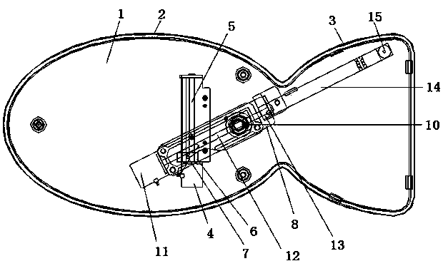
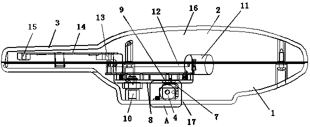
[0034] like figure 1 As shown, a mouth scanner includes a casing composed of a lower cover body 1 and an upper cover body 16 , and an upper cover body 16 that conforms to the lower cover body 1 is provided at the upper end of the lower cover body 1 . The lower cover 1 and the upper cover 16 are fixedly connected by a number of bolts, and sealing rings are provided at the connection holes of the bolts and on the connecting edge of the lower cover 1 and the upper cover 16, so as to prevent the saliva in the oral cavity from entering. inside the shell. The material of the sealing ring is preferably food-grade silica gel, and the housing includes a handle part 2 and a scanning part 3 that are integrally connected. The scanning part 3 is made of transparent material, and the transparent material is preferably transparent ABS plastic or plexiglass PMMA.

[0035] The lower cover body 1 and the upper cover body 16 both include a handle part 2 that is integrally connected and a scanni...

Embodiment 2

[0055] The only difference between this embodiment and Embodiment 1 is that the first lead screw 5 in Embodiment 1 is replaced by a first slide rail, and the first stepping motor 4 in Embodiment 1 is replaced by a first motor. The first sliding members located on the first sliding rail are connected to control the left and right movement of the first sliding member. One end of the movable plate 8 is also connected to the first sliding member, and the other end of the movable plate 8 is also connected to the first sliding member. The end head is rotatably connected to the shaft pin 10, the mouth scanner is a left-right symmetrical structure, and the shaft pin 10 is located on the symmetry line of the mouth scanner; the movable plate 8 is provided with a second motor and The second sliding rail, the second motor controls the second sliding member located on the second sliding rail to move along the length direction of the movable plate 8, and the second sliding member is connecte...

Embodiment 3

[0059] The difference between this embodiment and Embodiment 1 is only that the first stepping motor 4 and the second stepping motor 11 are replaced by a first stepping cylinder and a second stepping cylinder, respectively.


PUM


Abstract

The invention discloses an oral cavity scanning instrument. The oral cavity scanning instrument comprises a lower cover body (1), wherein the lower cover body (1) comprises an integrated connected handle part (2) and a transparent scanning part (3) which adopts the shape similar to that of the oral cavity; a horizontal moving unit which can be used for enabling one end of a moving plate (8) to move from left to right is arranged on the inner bottom surface of the handle part (2); the other end of the moving plate (8) is rotatably connected with a fixing shaft; a front-and-rear direction movingunit which moves in the length direction of the moving plate (8) is arranged on the moving plate (8), and is connected with a scanning arm (14) which extends in the direction towards the scanning part (3); a first camera (15) is connected to a free end of the scanning arm (14). According to the oral cavity scanning instrument provided by the invention, the oral cavity full scanning can be completed in one time without moving of the oral cavity scanning instrument.

Description

technical field [0001] The invention relates to an oral scanner, in particular to an oral scanner capable of scanning and photographing teeth, belonging to the technical field of electronic appliances. Background technique [0002] With the development of 3D graphic image technology, dental scanning is generally a graphic image acquisition scan at present. The structure of the existing oral scanner is generally the structure described in Chinese Patent No. 201610009864.9. For example, it includes a scanner host and a dental imaging head. The dental imaging head is small, so that it can be easily put into the oral cavity. During the scanning process, the doctor only needs to Hold the scanner host and make the dental scour head slide on the patient's teeth, and then the acquired 2D image can be reconstructed by 3D technology to obtain an accurate tooth scan. [0003] That is to say, the scanner host and the dental view head of the above structure are mobile, and the doctor co...

Claims


Application Information

Patent Timeline
Patent Type & Authority Applications(China)
IPC IPC(8): A61B5/00A61B1/04A61B1/24
CPCA61B1/00009A61B1/00029A61B1/00064A61B1/00131A61B1/04A61B1/24A61B5/0088
Inventor 李勇李佳芸赖珍华
Owner 李勇
Why Eureka
Try Eureka