A test system and method for atomization spraying effect of natural gas drag reducer

An effect test and drag reducer technology, which is applied in the field of natural gas drag reducer atomization spraying effect test system, can solve the problem of inability to accurately judge the effect of drag reducer atomization spraying, the inability to obtain the pipeline flow rate environment, and the inability to simulate the diameter of natural gas pipelines etc. to achieve reliable test results, simple test methods, and easy operation

Active Publication Date: 2021-08-31
CHINA PETROLEUM & CHEM CORP +1
View PDF19 Cites 0 Cited by
  • Summary
  • Abstract
  • Description
  • Claims
  • Application Information

AI Technical Summary

Problems solved by technology

[0005] However, the diameter of the natural gas pipeline in the actual site is often very thick (such as φ273), and the laboratory cannot simulate the diameter of the natural gas pipeline on site. It is impossible to obtain a relatively accurate flow rate environment in the pipeline, and thus cannot accurately judge the actual atomization spraying effect of the drag reducer

Method used


Image

  • A test system and method for atomization spraying effect of natural gas drag reducer

Examples


Embodiment 1

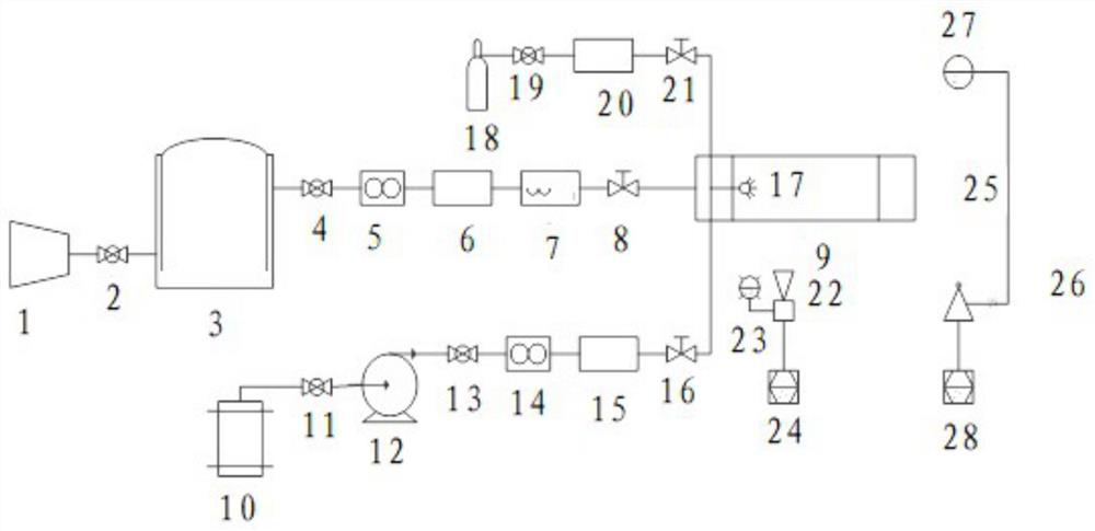
[0037] This embodiment provides a natural gas drag reducer atomization spraying effect test system, including: simulated pipeline system, atomization filling system, high-speed camera system and spray particle size measurement system;

[0038] Wherein, the atomization filling system is used for filling the drag reducer into the simulated pipeline system;

[0039] The high-speed camera system is used to collect atomized spray images;

[0040] The spray particle size measurement system is used to measure the particle size of the atomized particles of the drag reducer and its change with time, and automatically generate a "particle size-time" curve.

[0041] Further, the simulated piping system includes sequentially connected compressors, buffer tanks, gas flow meters, pressure sensors, temperature sensors, and transparent test pipe sections; in order to obtain better test results, ball valves, Valves such as precision regulating valves; for example, there are ball valves betwee...

Embodiment 2

[0049] This embodiment specifically illustrates the use of the test system to evaluate the atomized spraying effect of the drag reducer:

[0050] A natural gas pipeline is 50.54km long, with a design pressure of 4.0MPa, a pipe diameter of φ273, and a design capacity of 100 million standard cubic meters per year.

[0051] Due to seasonal peak shaving requirements, the pipeline adopts the method of atomizing and filling natural gas pipeline drag reducer to increase the transmission.

[0052] The specific process of evaluating the effect of atomized spraying of natural gas drag reducer is as follows:

[0053] 1. In order to be as close to the actual production as possible, before carrying out the evaluation of the atomization effect, the operating parameters of the simulated gas transmission pipeline must be determined, and the gas flow rate in the simulated pipeline is required to be similar to the flow rate in the actual pipeline.

[0054] According to the actual pipeline info...


PUM


Abstract

The invention relates to a system and method for testing the atomization spraying effect of a natural gas drag reducer. The test system includes: a simulated pipeline system, an atomization filling system, a high-speed camera system and a spray particle size measurement system; wherein, the atomization filling system is used to add drag reducer to the simulated pipeline system; The high-speed camera system is used to collect atomized spray images; the spray particle size measurement system is used to measure the particle size of the drag reducer atomized particles, and its change with time, and automatically generate a "particle size-time" curve. The atomization and spraying effect testing system and method of the natural gas drag reducing agent of the present invention can reasonably evaluate the atomization effect, and provide a basis for determining on-site filling process parameters.

Description

technical field [0001] The invention relates to the technical field of natural gas pipeline systems, in particular to a system and method for testing the atomization spraying effect of a natural gas drag reducer. Background technique [0002] Natural gas pipeline drag reducer is a pipeline additive, which belongs to an emerging pipeline drag reduction technology, and is mainly used for short-term increase in natural gas pipeline or seasonal peak shaving. Its working principle is that the natural gas drag reducer is adsorbed in the pipeline to form an elastic film, thereby reducing the roughness of the pipe wall, reducing the energy consumption of turbulent flow, and achieving the purpose of drag reduction. [0003] At present, most researches on natural gas drag reducers mainly focus on the synthesis and performance evaluation of drag reducers, but if the samples in the laboratory are to be applied industrially, it is necessary to develop effective Filling process. Feasibl...

Claims


Application Information

Patent Timeline
Patent Type & Authority Patents(China)
IPC IPC(8): G01D21/02B05B7/04
CPCB05B7/0416G01D21/02
Inventor 王晓司王晓霖赵巍李雪王佩弦高杭
Owner CHINA PETROLEUM & CHEM CORP
Why Eureka
Try Eureka