
Method and system for optimizing visual inertial speedometer

An odometer and vision technology, applied in the field of visual-inertial odometer optimization, can solve the problems of accumulation of positioning errors and inability to know the actual scale, etc.

Active Publication Date: 2020-02-07
EAST CHINA JIAOTONG UNIVERSITY
View PDF12 Cites 13 Cited by
  • Summary
  • Abstract
  • Description
  • Claims
  • Application Information

AI Technical Summary

Problems solved by technology

However, there is a scale problem in the monocular vision system, that is, the system cannot know the actual scale of the obtained motion process, and can only obtain relative length information, which will cause positioning errors to accumulate over time

Method used


Image

  • Method and system for optimizing visual inertial speedometer
  • Method and system for optimizing visual inertial speedometer
  • Method and system for optimizing visual inertial speedometer

Examples


Embodiment Construction

[0020] The technical solutions in the embodiments of the present application will be clearly and completely described below in conjunction with the drawings in the embodiments of the present application. Based on the embodiments in this application, all other embodiments obtained by persons of ordinary skill in the art without creative efforts fall within the protection scope of this application.

[0021] Real-time tracking of the position and attitude of devices in an unknown environment is one of the core issues in the fields of augmented reality, virtual reality, navigation and control, mobile robots, unmanned driving, and drones. As the most common method to solve such problems, Simultaneous Localization and Mapping (SLAM) has also been widely studied in related fields such as robotics and computer vision. Recently, localization algorithms based on the fusion of computer vision and inertial measurement units have received increasing attention due to their low cost, high ac...


PUM


Abstract

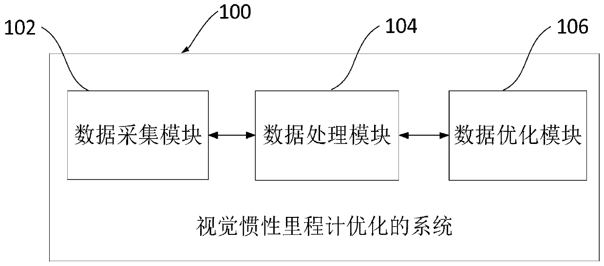
The embodiment of the invention discloses a method and system for optimizing a visual inertial speedometer. The method comprises the steps of obtaining IMU data and visual image data; extracting dotted line feature data of the visual image data; performing pre-integration processing on the IMU data to obtain scale information and IMU variables; performing joint initialization on the dotted line feature data based on the scale information to obtain a dotted line feature pixel gray value; calculating an IMU update amount between two adjacent frames of visual images; combining the IMU update amount to obtain a new pose; judging whether different frames of images meet target conditions or not; if so, obtaining a key frame; adding the key frame, the pose, the target dotted line feature data, pre-configured acceleration zero offset and gyro zero offset and an IMU speed to a sliding window to obtain marginalized prior; and obtaining an IMU residual error and a visual residual error, and performing optimization processing on visual image estimation based on the marginalized prior, the IMU residual and the visual residual error. The accumulation of errors can be eliminated to obtain an optimal trajectory of the visual images.

Description

technical field [0001] The present application relates to the technical field of autonomous navigation, and more specifically, to a method and system for visual-inertial odometry optimization. Background technique [0002] With the development of computer vision technology, visual odometry has become an important choice for autonomous mobile navigation systems due to its strong adaptability. In the pure visual odometer system, the system uses the camera sensor to obtain the image information of the surrounding environment, and estimates the motion state of the system by analyzing the image. However, there is a scale problem in the monocular vision system, that is, the system cannot know the actual scale of the obtained motion process, but can only obtain relative length information, which will cause positioning errors to accumulate over time. Contents of the invention [0003] In view of the above problems, the present application provides a method and system for optimizi...

Claims


Application Information

Patent Timeline
IPC IPC(8): G01C22/00G06T7/246G06T7/73
CPCG01C22/00G06T2207/10016G06T2207/30241G06T7/246G06T7/73
Inventor 姜楠黄德斌李进黄伟
Owner EAST CHINA JIAOTONG UNIVERSITY
Learn More