Material jacking device for stainless steel pipe shrinkage machine

The technology of a jacking device and a stainless steel pipe is applied in the field of jacking of a tube shrinking machine, which can solve the problem of fixing the installation position of the jacking device, and achieve the effects of convenient height adjustment, in place protective measures, and improved safety.

Inactive Publication Date: 2020-02-07
杨晨光
View PDF7 Cites 1 Cited by
  • Summary
  • Abstract
  • Description
  • Claims
  • Application Information

AI Technical Summary

Problems solved by technology

[0003] The object of the present invention is to provide a jacking device for a stainless steel tube shrinking machine in order to solve the above problems, which solves the problems of fixing the installation position of the existing jacking device

Method used


Image

  • Material jacking device for stainless steel pipe shrinkage machine
  • Material jacking device for stainless steel pipe shrinkage machine
  • Material jacking device for stainless steel pipe shrinkage machine

Examples


Embodiment Construction

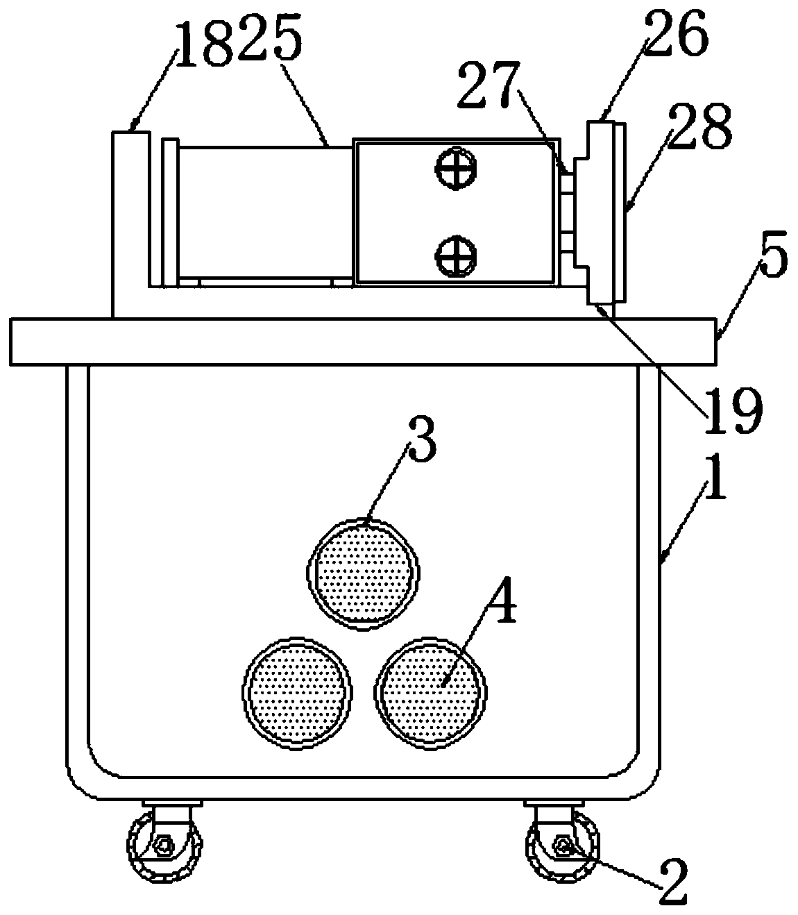
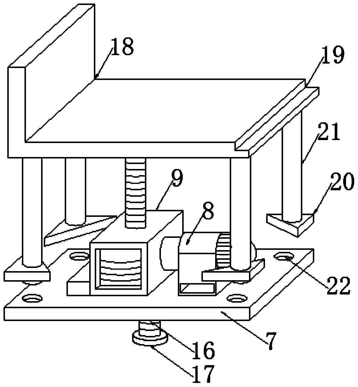
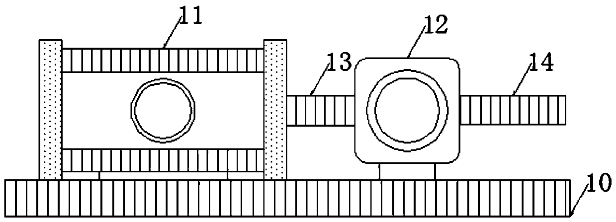
[0022] Such as Figure 1-7 As shown, this embodiment adopts the following technical solutions:

[0023] A jacking device for a stainless steel tube shrinking machine, comprising a storage box 1, the storage box 1 is designed in a square shape, and the four corners of the lower end surface of the storage box 1 are all treated with chamfered corners, and the storage box 1 Rollers 2 are fixedly installed at the four corners of the lower end surface of 1. The four rollers 2 have the same specifications and are distributed in a rectangular array. The upper end surface of the storage box 1 is provided with a square cavity 6. The storage box 1 The two opposite sides of the box 1 are connected to the square cavity 6 and are provided with three round holes 3. The three round holes 3 on the same side of the storage box 1 have the same specifications and are distributed in a triangular array. An air intake cover 4 is installed, and the upper end of the storage box 1 is fixedly equipped ...


PUM


Abstract

The invention discloses a material jacking device for a stainless steel pipe shrinkage machine. A storage box is included and designed in a cube manner. The four corners of the lower end face of the storage box are subjected to sphere corner chamfering treatment. Wheels are fixedly arranged at the positions of the four corners of the lower end face of the storage box, are consistent in specification and are distributed in a rectangular array manner. A square cavity is formed in the upper end face of the storage box in a penetration manner. The two opposite side faces of the storage box communicate with the square cavity and are each provided with three circular holes. The three circular holes in the same side face of the storage box are consistent in specification and are distributed in atriangular array manner, wherein each circular hole is internally provided with an air inlet cover. A protection surrounding plate is fixedly arranged at the upper end of the storage box. According tothe material jacking device for the stainless steel pipe shrinkage machine, the storage box is arranged to conduct safety protection on the material jacking device, and safety of the material jackingdevice is improved; and meanwhile, the height of the material jacking device is adjusted through a worm gear lead screw lifting mechanism, and accordingly adaptation to different work heights can beachieved.

Description

technical field [0001] The invention belongs to the technical field of jacking for tube shrinking machines, in particular to a jacking device for stainless steel tube shrinking machines. Background technique [0002] In daily use, the stainless steel tube shrinking machine needs to cooperate with the feeding device to continuously feed the pipes that need to be shrunk. The traditional stainless steel tube shrinking machine has the problems of fixed installation position, inconvenient height adjustment and lack of protection measures. For this problem, it is necessary to design a jacking device for a stainless steel tube shrinking machine. Contents of the invention [0003] The object of the present invention is to provide a jacking device for a stainless steel tube shrinking machine in order to solve the above problems, which solves the problems of the existing jacking device such as fixed installation positions. [0004] In order to solve the above problems, the present ...

Claims


Application Information

Patent Timeline
Patent Type & Authority Applications(China)
IPC IPC(8): B21C1/32B21C1/22
CPCB21C1/22B21C1/32
Inventor 杨晨光任新年
Owner 杨晨光
Why Eureka
Try Eureka