
Ship swaying platform for wind tunnel test

A technology of wind tunnel test and rocking table, applied in the field of wind tunnel test, can solve the problems of low reliability of calculation results, influence test accuracy, limited test range, etc., and achieve obvious controllability, compact and concise mechanism, and structure compact effect

Active Publication Date: 2020-02-04
LOW SPEED AERODYNAMIC INST OF CHINESE AERODYNAMIC RES & DEV CENT
View PDF6 Cites 5 Cited by
  • Summary
  • Abstract
  • Description
  • Claims
  • Application Information

AI Technical Summary

Problems solved by technology

Since the computer modeling and numerical simulation methods used in our country, especially the flow field coupling methods, are not yet perfect, the reliability of the calculation results is not very high, so the research on the air flow field related to dynamic aircraft-carrying ships mainly adopts the second method mentioned above. method
Secondly, due to the high cost of sea testing on real ships, the scope of testing is limited
Moreover, due to the complex structure of the existing general-purpose ship motion simulator, especially its large size, it is difficult to install it inside the wind tunnel test section. Even if it is installed in the wind tunnel, it will cause a large degree of blockage and affect the test accuracy; therefore, It is necessary to carry out the measurement of the dynamic ship airflow field in the wind tunnel, and the study of the suitability of the carrier-based ship and carrier-based aircraft. The current general-purpose ship motion simulator cannot meet the requirements.

Method used


Image

  • Ship swaying platform for wind tunnel test
  • Ship swaying platform for wind tunnel test

Examples


Embodiment Construction

[0029] In order to make the purpose, technical solution and advantages of the present invention clearer, the present invention will be further elaborated below in conjunction with the accompanying drawings.

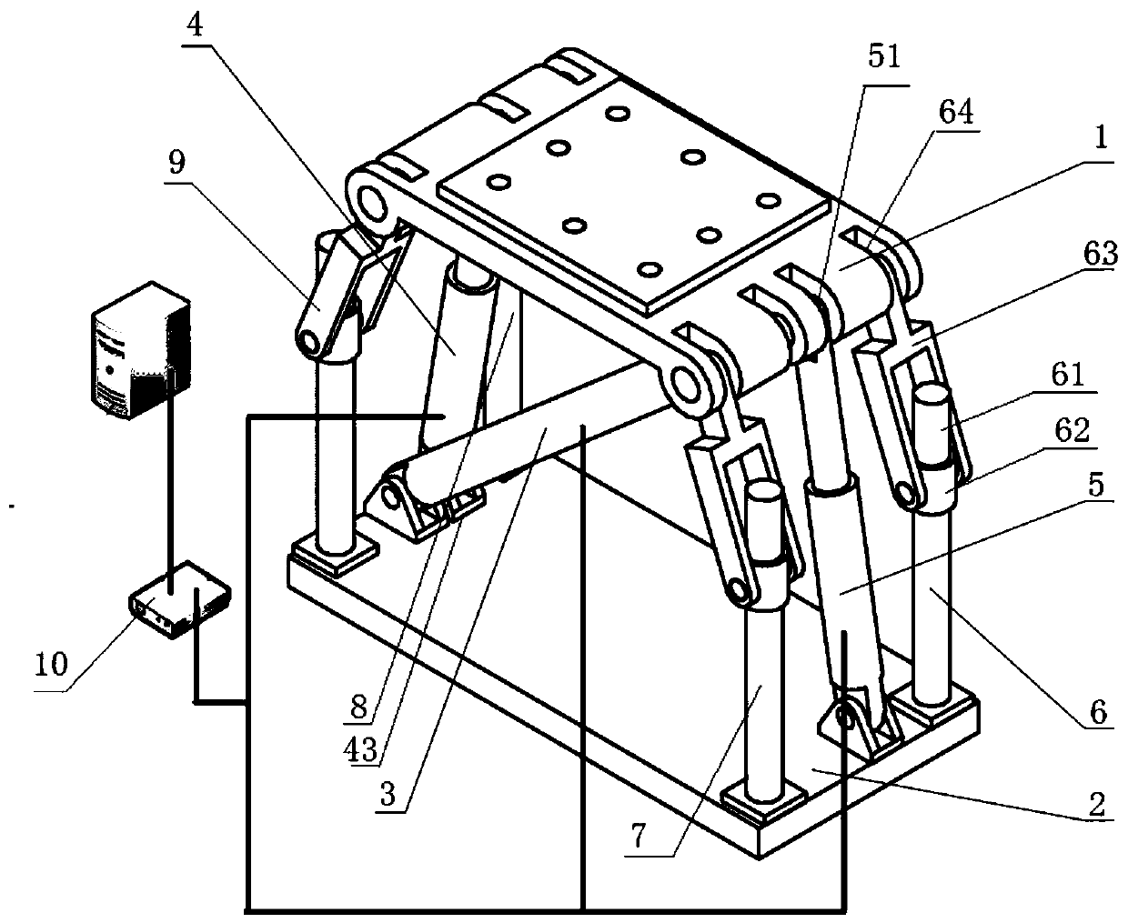
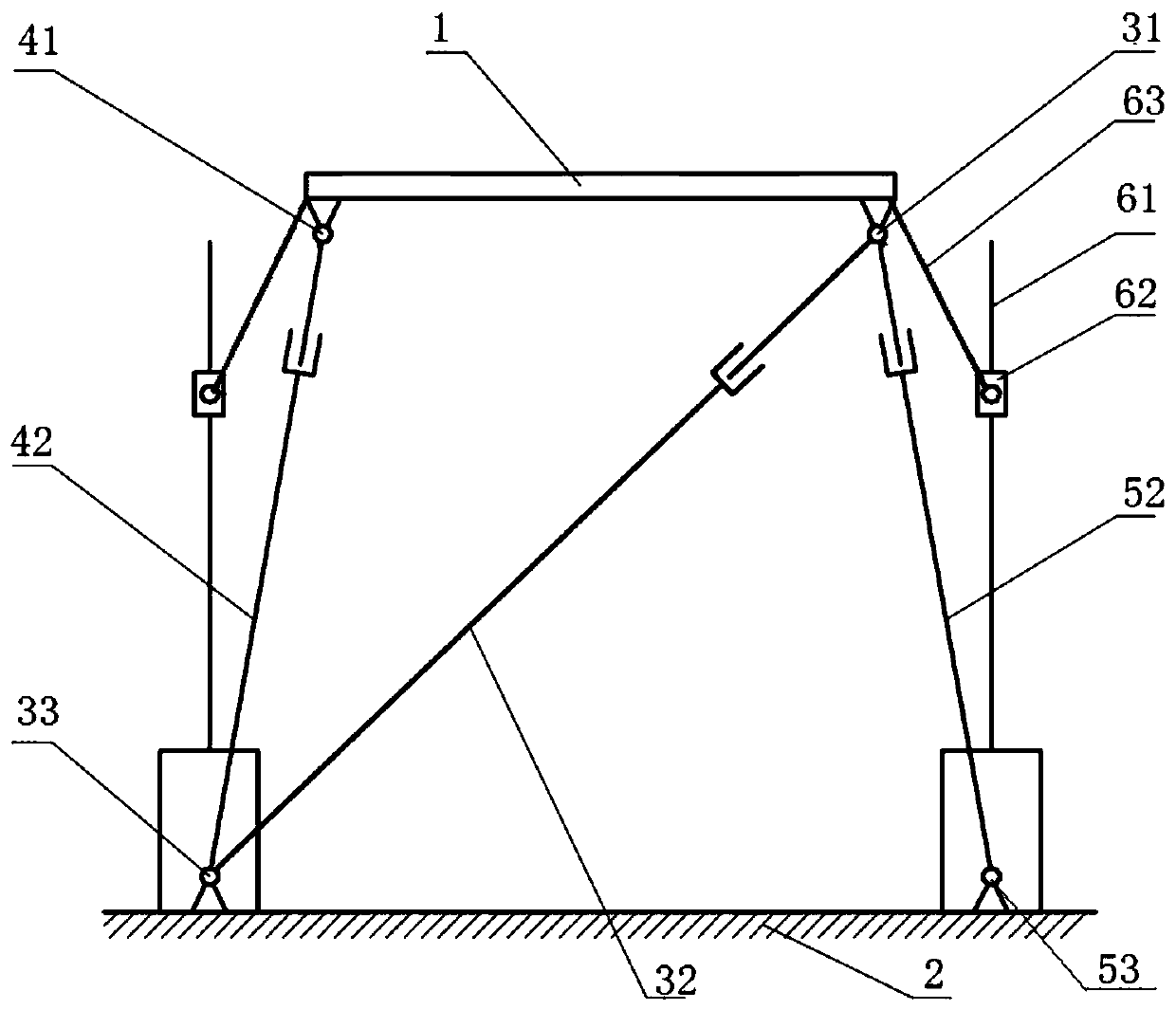
[0030] In this example, see figure 1 and figure 2 As shown, the present invention proposes a ship rocking platform for wind tunnel testing, including a kinematic mechanism, a follow-up mechanism, a moving platform 1, a base 2 and a motion controller 10; Between the platform 1 and the base 2, the motion controller 10 is connected to the motion mechanism through a cable, and drives the motion mechanism to perform controllable telescopic movement;

[0031] The motion mechanism includes RPR assembly I3, RPR assembly II4 and RPR assembly III5, and the RPR assembly I3, RPR assembly II4 and RPR assembly III5 are connected in parallel with each other, and are erected between the upper moving platform 1 and the lower base 2; The RPR component I3, RPR component II4 and RPR compo...


PUM


Abstract

The invention discloses a ship swaying platform for wind tunnel test. The ship swaying platform comprises a moving mechanism, a follow-up mechanism, a moving platform, a base and a motion controller;the moving mechanism and the follow-up mechanism are arranged between the moving platform and the base, the motion controller and the motion mechanism are connected through a cable to control the motion mechanism to perform controllable telescopic motion; and a main control computer of a wind tunnel transmits a posture control signal of a ship model to the motion controller through the cable, andthe motion controller controls a RPR component I, a RPR component II and a RPR component III to perform telescopic motion. The ship swaying platform can be used for simulating the motion of an aerialcarrier ship in the wind tunnel to form an air flow field above and around a flight deck of the aerial carrier ship, and conditions are provided for the measurement of the dynamic ship air flow fieldin the wind tunnel, the research of the adaptability of warships of the aerial carrier ship and a shipboard aircraft and the like. The different attitudes of the ship model in the wind tunnel flow field can be adjusted, and conditions are provided for the aerodynamic measurement of the ship model under different attitudes and the measurement of the surrounding airflow field.

Description

technical field [0001] The invention belongs to the technical field of wind tunnel tests, in particular to a ship swing table for wind tunnel tests. Background technique [0002] The safety of take-off and landing of carrier-based aircraft is one of the most dangerous actions on board aircraft-based ships, and it is also the first problem that must be solved for aircraft carriers to form combat effectiveness. Due to the complex air flow field above and around the flight deck, it will have a great impact on the stability of the carrier-based aircraft during take-off and landing, and even endanger the flight safety of the carrier-based aircraft. In order to avoid accidents and ensure the safety of take-off and landing, All naval powers attach great importance to and actively solve this problem. According to research, the main factors affecting the safety of carrier-based aircraft takeoff and landing include the seawater flow field, the movement of the carrier-based ship, and ...

Claims


Application Information

Patent Timeline
IPC IPC(8): G01M9/04G01M9/06
CPCG01M9/04G01M9/062
Inventor 张钧陈陆军傅澔武杰马军金华张晖梁勇刘江涛刘赟孙福振兰宇
Owner LOW SPEED AERODYNAMIC INST OF CHINESE AERODYNAMIC RES & DEV CENT
Learn More