Micro-hemispherical resonator gyro structure, assembly method and wafer fixture

A hemispherical resonant gyroscope and hemispherical resonance technology, which are applied in microstructure devices, processing microstructure devices, and microelectronic microstructure devices, etc., can solve the problems of low assembly accuracy, low assembly efficiency, poor assembly consistency, etc., and achieve assembly difficulty. Low, reduce assembly error, eliminate the effect of partial error

Inactive Publication Date: 2020-02-04
NAT UNIV OF DEFENSE TECH
View PDF5 Cites 7 Cited by
  • Summary
  • Abstract
  • Description
  • Claims
  • Application Information

AI Technical Summary

Problems solved by technology

[0005] In order to overcome the problems of low assembly accuracy, poor assembly consistency, and low assembly efficiency of the existing micro-hemispherical resonant gyroscope assembly technology, the present invention provides a wafer-level assembly method for a micro-hemispherical resonant gyroscope, which is based on the layout of the bottom plane electrodes, which can significantly Improve assembly accuracy, assembly consistency, stability and assembly efficiency

Method used


Image

  • Micro-hemispherical resonator gyro structure, assembly method and wafer fixture
  • Micro-hemispherical resonator gyro structure, assembly method and wafer fixture
  • Micro-hemispherical resonator gyro structure, assembly method and wafer fixture

Examples


Embodiment 1

[0047] A wafer-level assembly method for a micro-hemispherical resonant gyro structure, as shown in Figure 3, is suitable for high-precision assembly of a micro-hemispherical resonant gyro structure driven by a bottom plane electrode, and specifically includes the following steps:

[0048] Step 1, as shown in Figure 3 (a), open at least two through glass sheet positioning holes 9 on the edges of both ends of a plurality of glass sheets 8 containing the micro-hemispherical resonant structure 1, for realizing the micro-hemispherical resonant structure 1 in a circle Positioning on the sheet holder 10; in this embodiment, laser cutting is used to complete the opening of the glass sheet positioning holes 9, the number is two, and they are arranged symmetrically along the central axis of the glass sheet 8.

[0049] Step 2, as shown in Figure 3 (b), align the plurality of glass sheets 8 obtained after the processing in step 1 with the wafer holder 10 on the basis of the glass sheet po...

Embodiment 2

[0065] like figure 1 A kind of micro-hemispheric resonant gyroscope structure shown in and 3, comprises micro-hemispherical resonant structure 1, described micro-hemispherical resonant structure 1 is fixedly connected with planar electrode 2 through the anchor point of the center, in guaranteeing that micro-hemispherical resonant structure 1 and disc fixture 10. While having a sufficient contact area, it is compatible with the subsequent process. The planar electrode 2 is used to extract the vibration signal of the micro-hemispheric resonant gyro structure, and is an essential part of the micro-hemispheric resonant gyro structure;

[0066] There is a gap between the two ends of the micro-hemispherical resonant structure 1 and the planar electrode 2, and the planar electrode 2 is provided with grooves corresponding to the two ends of the micro-hemispheric resonant structure 1 to form a gap for realizing the micro-hemispheric resonant gyro structure Electrostatic drive and capac...

Embodiment 3

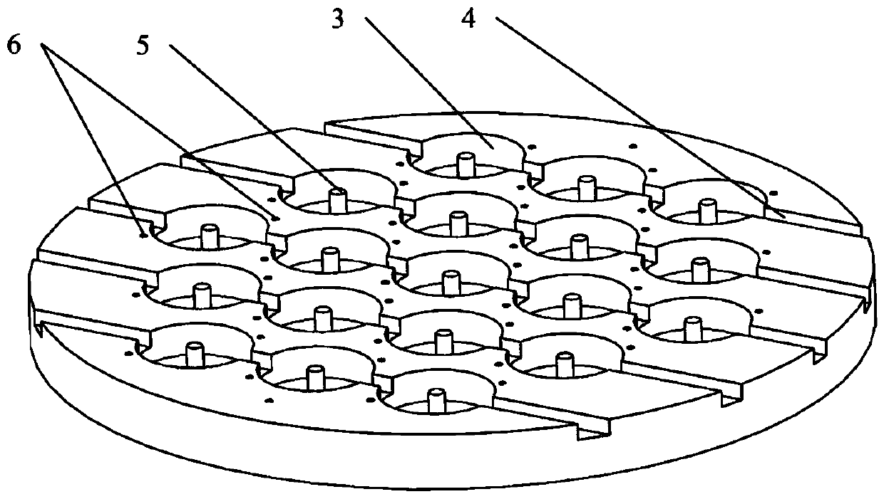
[0076] like figure 2 A wafer clamp of a micro-hemispherical resonant structure shown in -3 includes a clamp body, and the clamp body is provided with a plurality of space-avoiding grooves 3 that cooperate with the micro-hemispherically resonant structure 1, and the space-avoiding grooves 3 There are outlet grooves 4 on both sides, which are used to realize the inflow of gas and / or liquid required in the assembly process and the outflow of waste gas and / or waste liquid, so as to ensure the normal progress of the processing process;

[0077] The geometric center of each said avoidance groove 3 is provided with a fixed cylinder 5, that is, a fixed cylinder 5 is correspondingly installed in one avoidance groove 3, which is used to fix the micro-hemispherical resonant structure 1, and the fixed cylinder 5 The height is consistent with the depth of the escaping groove 3, which is convenient for placing the glass sheet 8 to pressurize the glass sheet 8 by the plane plate 7;

[0078...


PUM


Abstract

The invention relates to a micro-hemispherical resonator gyro structure, an assembly method and a wafer fixture. The invention discloses a micro-hemispherical resonator gyro structure wafer level assembly method, comprising the following steps: performing high temperature softening deformation machining and forming on independently manufactured glass sheets, then forming a micro-hemispherical resonant structures in the middle of each glass sheet, cutting glass sheet locating holes at the two ends of each glass sheet by adopting laser cutting, and by taking the locating holes as a benchmark, aligning multiple micro-hemispherical resonant structures which are the same and fixing the same micro-hemispherical resonant structures on the wafer fixture; and then performing operations by taking the wafer fixture as a unit, and completing subsequent processes, namely micro-hemispherical resonant structure releasing, surface metallization, fixation with a planar electrode, separation from the wafer fixture as well as cleaning, thus the micro-hemispherical resonator gyro structure driven by the planar electrode at the bottom is obtained. The micro-hemispherical resonator gyro structure waferlevel assembly method disclosed by the invention fixes and mounts multiple independently manufactured micro-hemispherical resonant structures on the same wafer fixture, a wafer level mounting operation is realized, an assembly error of the micro-hemispherical resonator gyro structure can be obviously reduced, stability and consistency of the processes as well as assembly efficiency are improved.

Description

technical field [0001] The invention relates to the technical field of micro-electromechanical system manufacturing, in particular to a microhemispherical resonant gyro structure, an assembly method for the microhemispherical resonant gyro structure, and a wafer fixture for the microhemispherical resonant gyro structure. Background technique [0002] Gyroscopes are sensors that measure the angular motion of carriers in inertial space. They are the basic core components of inertial navigation and attitude measurement systems. They have very important application values ​​in precision guidance, unmanned systems, oil exploration, stable platforms, and space vehicles. [0003] Resonant gyroscope is a kind of gyroscope, which has the advantages of less parts, high reliability and long working life, and has been widely used. The micro-hemispheric resonant gyroscope is a new type of resonant gyroscope. The manufacturing technology of the micro-hemispherical resonant gyroscope inclu...

Claims


Application Information

Patent Timeline
IPC IPC(8): G01C19/5691G01C19/5783G01C25/00
CPCG01C19/5691G01C19/5783G01C25/00B81C3/001B81B2201/0242B81B2201/0271G01C19/5769B81B7/007G01C19/5755
Inventor 吴学忠肖定邦席翔吴宇列何汉辉石岩卢坤李斌陈绎默袁超聂豹
Owner NAT UNIV OF DEFENSE TECH
Why Eureka
Try Eureka