Hydraulic oil pump for engineering machinery

A hydraulic oil pump and engineering machinery technology, applied in the field of hydraulic oil pumps, can solve problems affecting the working efficiency of construction machinery, inconvenient use, and oil pumps that cannot be used normally, and achieve the effects of avoiding abnormal use, convenient use, and avoiding work efficiency

Inactive Publication Date: 2020-02-04
合肥宇创液压件有限公司
View PDF10 Cites 2 Cited by
  • Summary
  • Abstract
  • Description
  • Claims
  • Application Information

AI Technical Summary

Problems solved by technology

[0003] The hydraulic oil pump for construction machinery is one of many kinds of hydraulic oil pumps. Since the working environment of construction machinery is mostly outdoors, the hydraulic oil pumps for construction machinery in the prior art are mostly affected by the outdoor air temperature when they are actually used. When the inside of the oil pump is lower than 10°C or higher than 50°C, the oil pump will not work normally, which is inconvenient to use and affects the working efficiency of construction machinery

Method used


Image

  • Hydraulic oil pump for engineering machinery
  • Hydraulic oil pump for engineering machinery
  • Hydraulic oil pump for engineering machinery

Examples


Embodiment 1

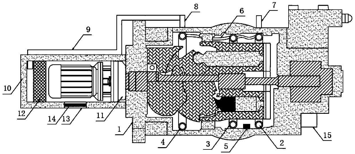
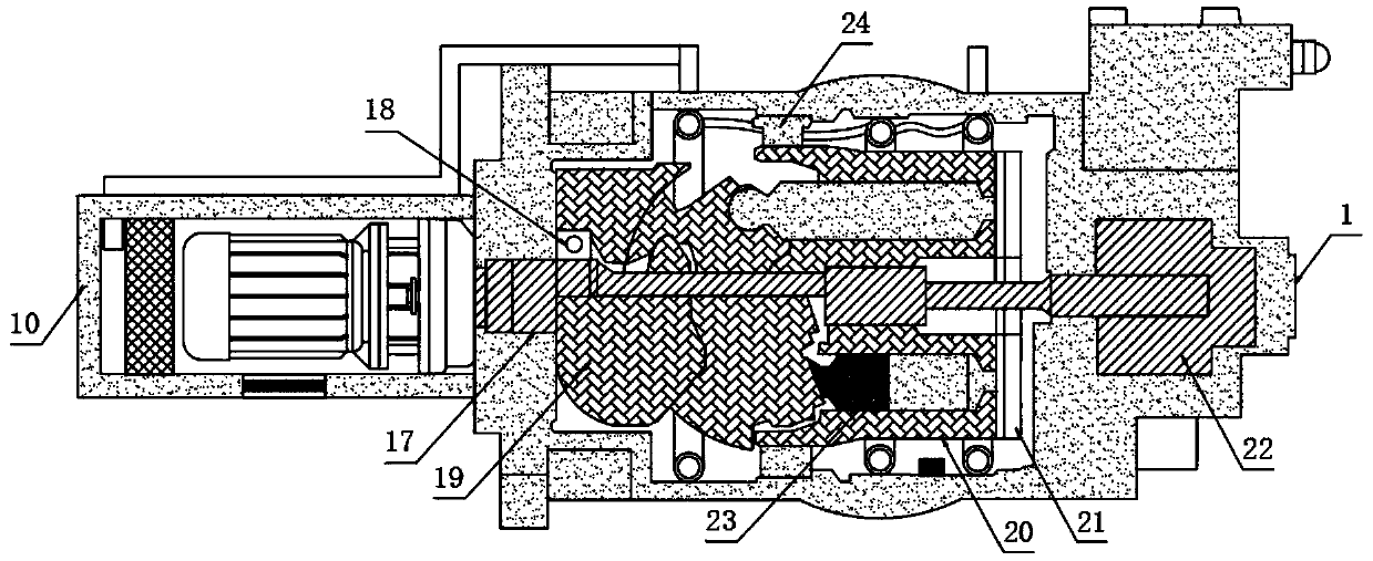
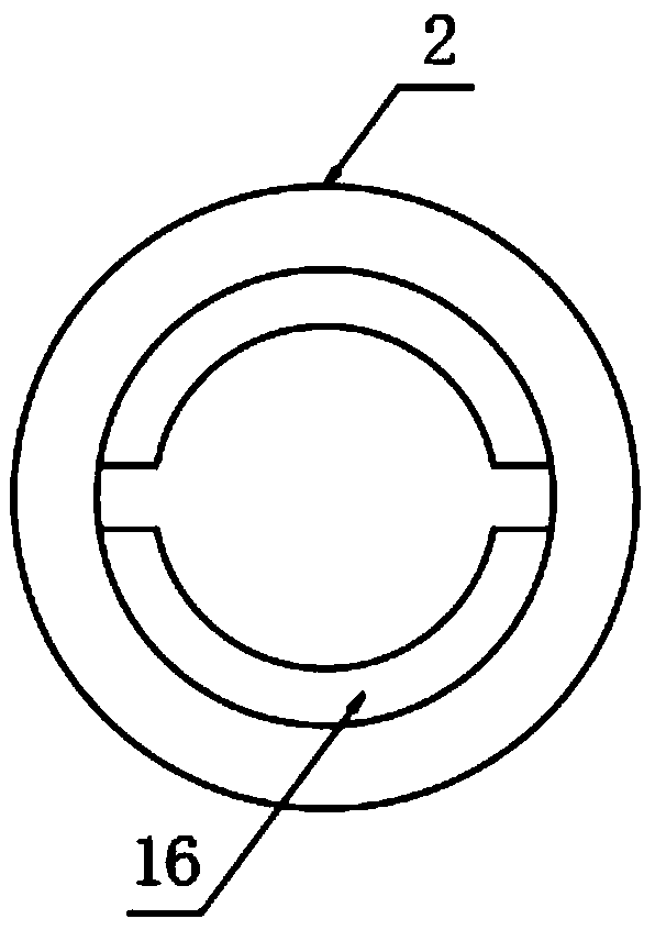
[0024] The present invention provides such Figure 1-3 A hydraulic oil pump for construction machinery shown includes a pump casing 1, a first annular copper pipe 2, a second annular copper pipe 3 and a third annular copper pipe 4 are arranged on the inner wall of the pump casing 1, and the first annular copper pipe 4 is arranged on the inner wall of the pump casing 1. A temperature detection unit 5 is arranged between the annular copper pipe 2 and the second annular copper pipe 3, between the first annular copper pipe 2 and the second annular copper pipe 3 and between the second annular copper pipe 3 and the third annular copper pipe 4 are connected with drainage hoses 6, and the inner walls of the first annular copper pipe 2, the second annular copper pipe 3 and the third annular copper pipe 4 are fixed with cooling fins 16, and the top of the pump casing 1 is provided with There is an air outlet 7 and an air inlet 8, the air inlet 8 is located on the side of the air outlet ...

Embodiment 2

[0027] Further, in the first embodiment above, the second annular copper pipe 3 is arranged on the side of the first annular copper pipe 2 , and the third annular copper pipe 4 is arranged on the side of the third annular copper pipe 4 .

[0028] Further, in the above-mentioned embodiment 1, the first annular copper pipe 2, the second annular copper pipe 3, the third annular copper pipe 4 and the temperature detection unit 5 are all fixedly connected to the inner wall of the pump casing 1, so as to facilitate the An annular copper pipe 2, a second annular copper pipe 3, a third annular copper pipe 4 and a temperature detection unit 5 are fixed.

[0029] Further, in the above-mentioned embodiment 1, the gas outlet 7 runs through the top of the pump casing 1 and extends to the inside of the pump casing 1 to communicate with the first annular copper pipe 2, so that the gas inside the first annular copper pipe 2 can be released from the outlet. Port 7 is exhausted.

[0030] Furth...


PUM


Abstract

The invention discloses a hydraulic oil pump for engineering machinery. The hydraulic oil pump comprises a pump housing, wherein a first annular copper pipe, a second annular copper pipe and a third annular copper pipe are arranged on the inner wall of the pump housing; a temperature detecting unit is arranged between the first annular copper pipe and the second annular copper pipe; draining hosesare connected both between the first annular copper pipe and the second annular copper pipe and between the second annular copper pipe and the third annular copper pipe; chilling plates are fixedly arranged on the inner walls of all of the first annular copper pipe, the second annular copper pipe and the third annular copper pipe; the top of the pump housing is provided with an air outlet and anair inlet; the air inlet is arranged at one side of the air outlet; the end part of the air inlet is provided with a transmission pipeline; a thermal insulating shell is fixedly arranged on the side surface of the pump housing; and a motor and a cooling fan are arranged in the thermal insulating shell. The hydraulic oil pump has the advantages that engine oil can be heated, so that the temperatureof the oil is prevented from being too low; and at the same time, the oil temperature can be reduced, the use is very convenient, and the working efficiency of engineering machinery can be effectively prevented from being affected.

Description

technical field [0001] The invention relates to the technical field of hydraulic oil pumps, in particular to a hydraulic oil pump for engineering machinery. Background technique [0002] The hydraulic oil pump is the power source in the hydraulic system. The hydraulic oil pump we choose should meet the pressure and flow requirements of the hydraulic system. At the same time, we must also fully consider the reliability, life, maintainability, etc. so that the selected hydraulic oil pump can be used in the hydraulic system. For medium and long-term operation, there are many types of hydraulic oil pumps and their characteristics are also very different. [0003] The hydraulic oil pump for construction machinery is one of many kinds of hydraulic oil pumps. Since the working environment of construction machinery is mostly outdoors, the hydraulic oil pumps for construction machinery in the prior art are mostly affected by the outdoor air temperature when they are actually used. W...

Claims


Application Information

Patent Timeline
Patent Type & Authority Applications(China)
IPC IPC(8): F04B53/08F04B53/18F15B21/0423F15B21/0427
CPCF04B53/08F04B53/18F15B21/042
Inventor 魏方毅
Owner 合肥宇创液压件有限公司
Why Eureka
Try Eureka