
Portable fault indicator detection and distribution network fault simulation device

A fault simulation device and fault indicator technology, which is applied in the direction of measuring devices, instruments, and measuring electrical variables, etc., can solve the problem of failure to meet the detection of transient wave recording type fault indicator wave recording performance, and does not have fault point synchronization fault simulation function, high voltage level, etc., to achieve the effect of convenient on-site testing, portability and convenient detection

Inactive Publication Date: 2020-01-31
STATE GRID HEBEI ELECTRIC POWER RES INST +2
View PDF8 Cites 3 Cited by
  • Summary
  • Abstract
  • Description
  • Claims
  • Application Information

AI Technical Summary

Problems solved by technology

Existing portable fault indicator detection devices are based on the design of non-transient wave recording type fault indicators, which cannot meet the detection of wave recording performance of transient state wave recording type fault indicators. Most of the existing portable fault indicator detection devices are single No output, no synchronous fault simulation function for upstream and downstream of the fault point
The existing principle of wave recording function and performance testing of transient wave recording type fault indicators is based on the method of generating high voltage analog line electric field, the equipment voltage level is high, there are potential safety hazards in field testing, and the portability is poor

Method used

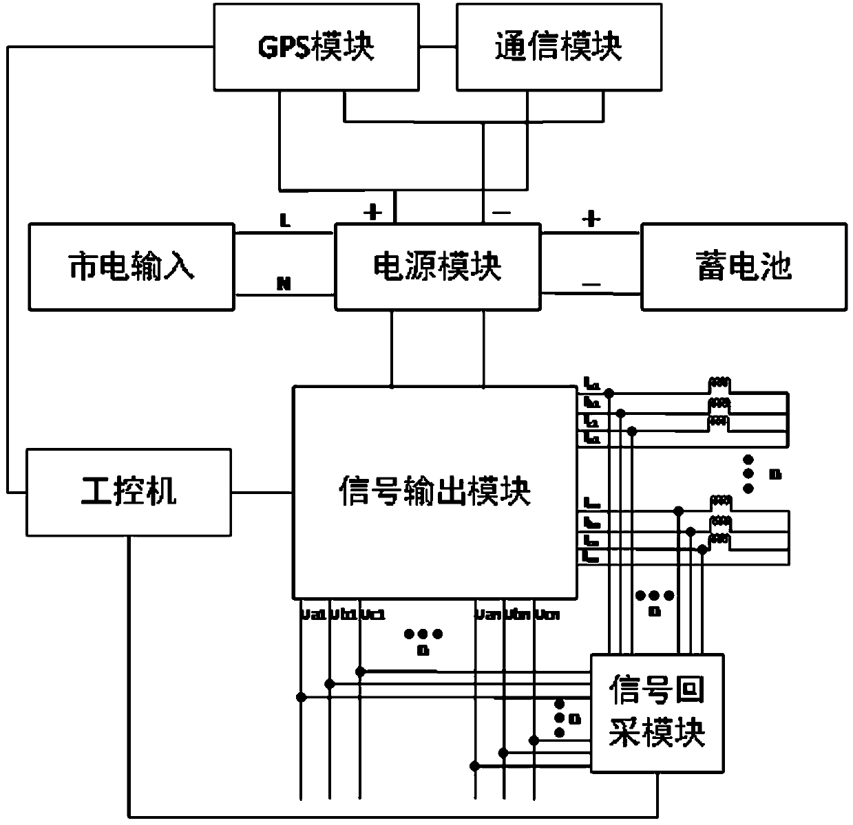

Image

  • Portable fault indicator detection and distribution network fault simulation device
  • Portable fault indicator detection and distribution network fault simulation device
  • Portable fault indicator detection and distribution network fault simulation device

Examples


Embodiment Construction

[0031] The following will clearly and completely describe the technical solutions in the embodiments of the application with reference to the drawings in the embodiments of the application. Apparently, the described embodiments are only some of the embodiments of the application, not all of them. The following description of at least one exemplary embodiment is merely illustrative in nature and in no way serves as any limitation of the application, its application or uses. Based on the embodiments in this application, all other embodiments obtained by persons of ordinary skill in the art without creative efforts fall within the protection scope of this application.

[0032] It should be noted that the terminology used here is only for describing specific implementations, and is not intended to limit the exemplary implementations according to the present application. As used herein, unless the context clearly dictates otherwise, the singular is intended to include the plural, a...


PUM


Abstract

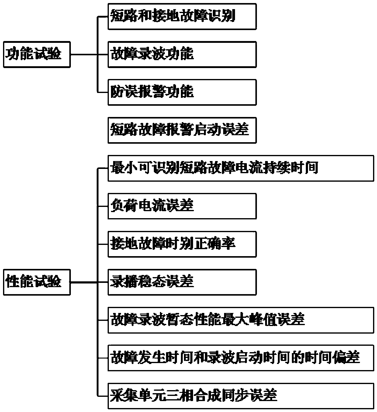
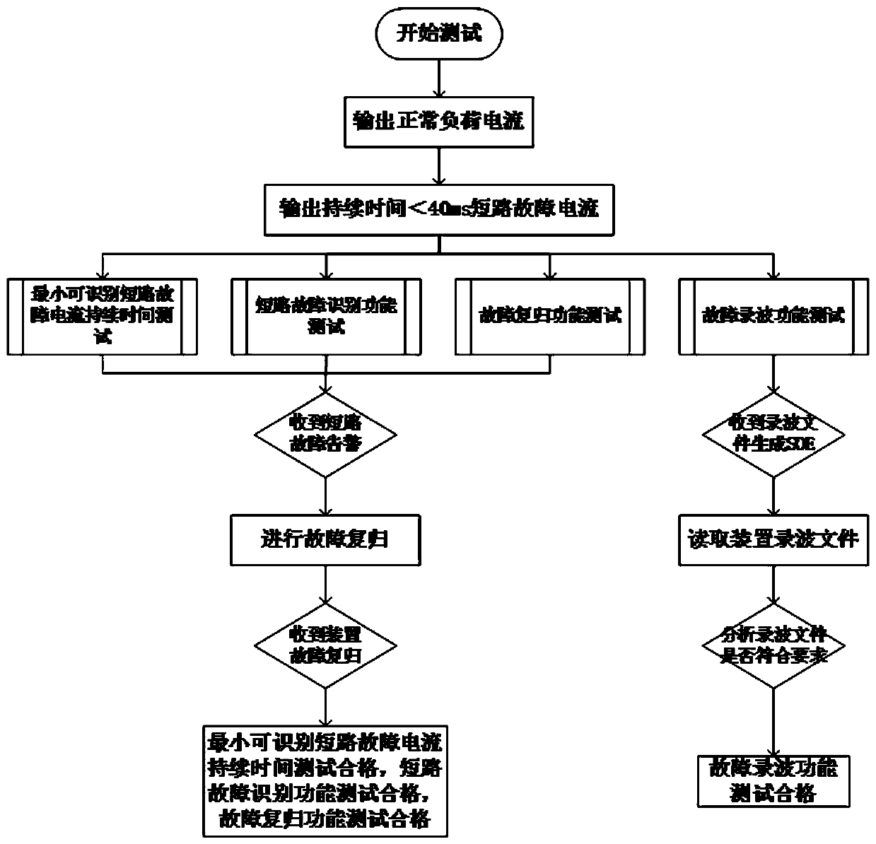
The invention discloses a portable fault indicator detection and distribution network fault simulation device which comprises a power supply module, a storage battery, a communication module, a GPS module, a signal output module, a signal recovery and wave recording module, an industrial personal computer and a fault indicator test frame. And the industrial personal computer is in communication connection with the signal output module and the signal recovery and wave recording module. According to the invention, on-site detection can be effectively carried out on the fault indicator in the range of a power grid company; especially for a transient recording type fault indicator, a method for starting the recording function of a transient recording type fault indicator at low voltage is adopted, so that the field test risk increase caused by the traditional method for simulating the electric field intensity of a line at high voltage is avoided; and the performance test of the transient recording type fault indicator is realized. For an improved detection project process, a method of combining fault indicator function testing with performance testing is adopted, so that repeated projects are reduced, the testing time is greatly shortened, the waiting time of field testing personnel is shortened, and the detection efficiency is improved.

Description

technical field [0001] The invention belongs to the detection technology of the operating state of a high-voltage circuit breaker, relates to the field of detection of the health state of an energy storage device of a high-voltage circuit breaker, and in particular relates to a portable fault indicator detection and distribution network fault simulation device. Background technique [0002] In recent years, overhead transient recording type fault indicators have been widely used, and the detection tasks of fault indicators are increasing year by year. The detection of fault indicators is generally carried out in the provincial electric power research institute. It takes a long time to detect the device, and is limited by the number of detection platforms configured by the provincial electric power research institutes, which often cannot meet the detection requirements, resulting in project delays and other problems. Most of the existing fault indicator detection platforms ar...

Claims


Application Information

Patent Timeline
Patent Type & Authority Applications(China)
IPC IPC(8): G01R35/00
CPCG01R35/00
Inventor 段昕贾伯岩马天祥贾静然张姿姿景皓姬艳鹏
Owner STATE GRID HEBEI ELECTRIC POWER RES INST
Learn More