A kind of thermal hydrolysis method of sludge
A technology of thermal hydrolysis and sludge, which is applied in the fields of pyrolysis sludge treatment, dewatering/drying/concentrating sludge treatment, and by-product vaporization, etc. problem, to achieve the effect of improving the effect and preventing scaling
Active Publication Date: 2022-06-03
浙江绿治环保技术有限公司 +1
View PDF5 Cites 0 Cited by
- Summary
- Abstract
- Description
- Claims
- Application Information
AI Technical Summary
Problems solved by technology
In this method, since the inner diameter of the sludge conveying pipeline 3 is much smaller than the diameter of the tank body, an agitator cannot be installed inside the sludge conveying pipeline 3, so that the sludge is heated unevenly in the sludge conveying pipeline 3, and the sludge Sludge is prone to sluggishness in the sludge conveying pipeline 3, and the inner wall is prone to fouling, which further reduces the heat transfer efficiency
Method used
View moreImage
Smart ImageViewing Examples

Examples
Embodiment Construction
[0033] In order to make the technical solutions of the present invention clearer, the present invention is described in detail below in conjunction with accompanying drawings 1 to 4.
Login to View More PUM
 Abstract
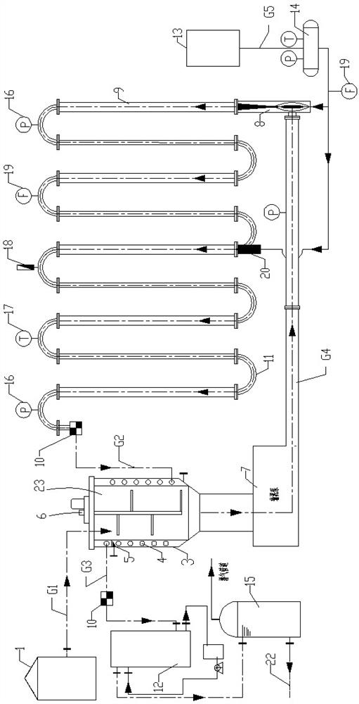
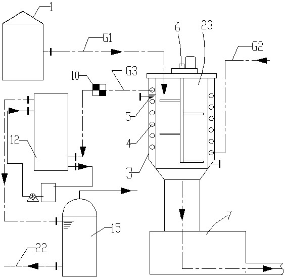
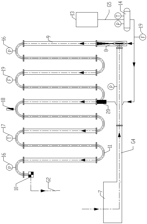
The invention discloses a thermal hydrolysis method of sludge, which comprises the following steps: the step of quickly and fully mixing the sludge to be treated with steam, passing the sludge to be treated with a certain pressure into the first inlet of the steam sludge injector, At the same time, steam with a certain pressure and temperature is passed into the second inlet of the sludge injector, and the sludge to be treated and steam are quickly and fully mixed in the sludge injector and then enter the sludge thermal hydrolysis pipeline; The step of thermal hydrolysis in the sludge thermal hydrolysis pipeline is to control the thermal hydrolysis temperature in the sludge thermal hydrolysis pipeline at 110-225°C, control the pressure at 0.5-3Mpa, and the reaction time is 0.1-1 hour. The sludge flows out through the pressure release device at the sludge outlet. The thermal hydrolysis method of sludge of the present invention can rapidly realize sufficient mixing of steam and sludge, has high heat transfer efficiency, and is energy-saving and environment-friendly.
Description
A kind of thermal hydrolysis method of sludge technical field The present invention relates to a kind of thermal hydrolysis method of sludge. Background technique The thermal hydrolysis of sludge refers to: under certain temperature and pressure conditions, the sludge is heated in a closed container, The sludge flocs are disintegrated, the cells are broken, organic matter is released, and macromolecules are hydrolyzed. Settling performance, dehydration performance and biodegradation performance can effectively improve the efficiency and quality of subsequent anaerobic digestion. Existing sludge thermal hydrolysis method mainly contains following two kinds: 1, sludge will be passed into tank body first, then steam will be passed into tank body, use mixer to stir sludge simultaneously, make sludge and The steam is mixed, and the steam heats the sludge and makes the tank have a certain pressure, so that the sludge undergoes a thermal hydrolysis reaction in the tank. ...
Claims
Login to View More Application Information
Patent Timeline
 Patent Type & Authority Patents(China)
IPC IPC(8): C02F11/13C02F11/10
CPCC02F11/13C02F11/10Y02W10/40
Inventor 童明彭如初郁聪郑卓峰王志刚陆建忠曹黎袁芳张俊昊孟云芳张健丁施佳陈俊宇钟军良张金泉
Owner 浙江绿治环保技术有限公司
Features
- R&D
- Intellectual Property
- Life Sciences
- Materials
- Tech Scout
- Unparalleled Data Quality
- Higher Quality Content
- 60% Fewer Hallucinations
Learn More Browse by: Latest US Patents, China's latest patents, Technical Efficacy Thesaurus, Application Domain, Technology Topic, Popular Technical Reports.
© 2025 PatSnap. All rights reserved.Legal|Privacy policy|Modern Slavery Act Transparency Statement|Sitemap|About US| Contact US: help@patsnap.com