Adjustable reducing pipe sludge continuous pyrohydrolysis device

A thermal hydrolysis and different-diameter pipe technology, which is applied in the direction of pyrolysis treatment of sludge and by-product vaporization, can solve problems such as sluggishness, uneven heating, and reduced heat transfer efficiency, so as to prevent scaling and thermal hydrolysis Effect of effect improvement

Pending Publication Date: 2020-01-24
浙江绿治环保技术有限公司 +1
View PDF2 Cites 2 Cited by
  • Summary
  • Abstract
  • Description
  • Claims
  • Application Information

AI Technical Summary

Problems solved by technology

Since the inner diameter of the sludge conveying pipeline 3 is much smaller than the diameter of the tank body, the agitator cannot be installed inside the sludge conveying pipeline 3, so that the sludge is heated unevenly in the sludge conveying pipeline 3, and the sludge is in the sludge Sluggishness is prone to occur in the conveying pipeline 3, and the inner wall is prone to fouling, which further reduces the heat transfer efficiency

Method used


Image

  • Adjustable reducing pipe sludge continuous pyrohydrolysis device
  • Adjustable reducing pipe sludge continuous pyrohydrolysis device
  • Adjustable reducing pipe sludge continuous pyrohydrolysis device

Examples


Embodiment 1

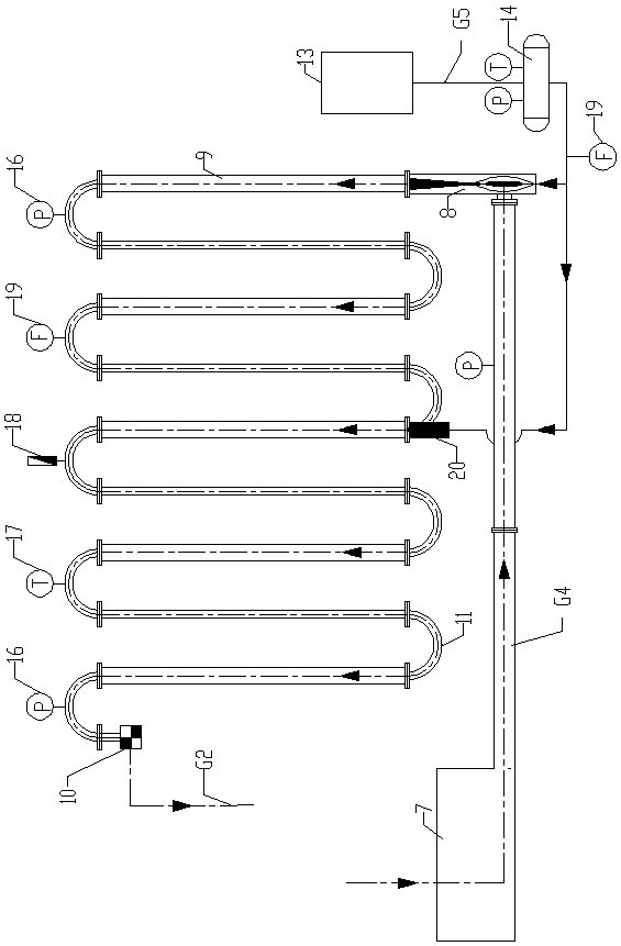
[0023] The present invention is an adjustable different-diameter pipe sludge continuous thermal hydrolysis device. A plurality of cylindrical pipes 9 with different inner diameters are connected to form a sludge thermal hydrolysis pipeline. The outlet of the device 8 is connected, the mud outlet of the mud delivery pump 7 is connected with the first inlet of the steam sludge injector 8 through the mud feeding pipeline BG4, and the steam supply port of the steam source 13 is connected with the steam sludge injector 8 through the steam supply pipeline CG5. The second inlet of the sludge thermal hydrolysis pipeline is connected with a pressure relief discharge device 10 at the thermal hydrolysis sludge outlet of the sludge thermal hydrolysis pipeline, and the pressure relief discharge device 10 leads to the pyrolysis sludge storage tank 15 through the discharge pipeline DG2.

[0024] Preferably, a plurality of cylindrical pipes 9 with different inner diameters are connected throug...

Embodiment 2

[0028] This embodiment is a sludge thermal hydrolysis system including the above-mentioned adjustable reducing pipe sludge continuous thermal hydrolysis device:

[0029] A sludge thermal hydrolysis system, comprising a sludge storage tank 1 filled with sludge to be treated, a sludge preheating device 23, a sludge delivery pump 7, a steam source 13, and a pyrolysis sludge storage tank 15, characterized in that: A sludge thermal hydrolysis pipeline and a steam sludge injector 8 are also provided. The sludge outlet to be treated in the sludge storage tank 1 communicates with the feed port of the sludge preheating device 23 through the sludge inlet conveying pipeline AG1, and the sludge preheater The discharge port of the thermal device 23 is connected with the mud inlet of the mud pump 7, and the mud outlet of the mud pump 7 is connected with the first inlet of the steam sludge ejector 8 through the mud inlet pipeline BG4, and the steam supply port of the steam source 13 The seco...


PUM


Abstract

The invention discloses an adjustable reducing pipe sludge continuous pyrohydrolysis device. According to the adjustable reducing pipe sludge continuous pyrohydrolysis device, a sludge pyrohydrolysispipeline is composed of a plurality of cylindrical pipelines with different inner diameters; an inlet of the sludge pyrohydrolysis pipeline is communicated with an outlet of a steam sludge ejector; asludge outlet of a sludge conveying pump is communicated with a first inlet of the steam sludge ejector through a sludge inlet conveying pipeline B, a steam supply port of a steam source is communicated with a second inlet of the steam sludge ejector through a steam supply pipeline C, a pyrohydrolysis sludge outlet of the sludge pyrohydrolysis pipeline is provided with a pressure relief discharger, and the pressure relief discharger is communicated with a pyrolysis sludge storage tank through a discharging pipeline D. The adjustable reducing pipe sludge continuous pyrohydrolysis device is simple in structure, relatively low in cost, high in pyrohydrolysis efficiency, energy-saving and environment-friendly.

Description

technical field [0001] The invention relates to an adjustable continuous thermal hydrolysis device for reducing pipe sludge. Background technique [0002] Thermal hydrolysis device is a commonly used equipment for thermal hydrolysis treatment of municipal sludge. The thermal hydrolysis of sludge refers to: under certain temperature and pressure conditions, the sludge is heated in a closed container to disintegrate the sludge flocs, rupture the cells, release organic matter, hydrolyze macromolecules, and process them through thermal hydrolysis. , can improve the sedimentation performance, dehydration performance and biodegradation performance of the sludge, so as to effectively promote the subsequent anaerobic digestion efficiency. [0003] The Chinese utility model patent with the application number 201220058583.X discloses "A Slurry Reactor for a Sludge Hydrothermal Drying Treatment Device", which describes "a Sludge Hydrothermal Drying Treatment Device". The muddy water ...

Claims


Application Information

Patent Timeline
IPC IPC(8): C02F11/10
CPCC02F11/10Y02W10/40
Inventor 童明彭如初郁聪郑卓峰王志刚陆建忠曹黎袁芳张俊昊孟云芳张健丁施佳陈俊宇钟军良张金泉
Owner 浙江绿治环保技术有限公司
Why Eureka
Try Eureka