Electric flocculation oil-water separator

An oil-water separator and water separator technology, which can be used in flocculation/sedimentation water/sewage treatment, water/sewage treatment, chemical instruments and methods, etc. Achieve the effect of improving water treatment efficiency and slowing down the flow rate of water flow

Pending Publication Date: 2020-01-31
北京丰舜通环保科技有限公司
View PDF0 Cites 1 Cited by
  • Summary
  • Abstract
  • Description
  • Claims
  • Application Information

AI Technical Summary

Problems solved by technology

The grease trap uses the different density of oil and water in the sewage to achieve the purpose of oil-water separation, but this method occupies a large area, and the oil removal efficiency is low, and the water quality stays in the grease trap for too long, which may easily lead to organic matter corruption , producing an odor
The coagulation dosing method is to put coagulants such as aluminum salts and iron salts into the sewage, so that the colloidal particles in the sewage are bonded and aggregated, and the grease and suspended particles are converted into sludge and precipitated; this method mixes The dosage of the coagulant is not easy to control, and the added medicament is prone to secondary pollution
The air flotation method uses highly dispersed micro-bubbles as a carrier to adhere to suspended matter, and the oil stains are floated to the water surface through the air bubbles to achieve the purpose of removing oil stains; however, this method has a high operating component and a large amount of scum, making oil recovery difficult

Method used


Image

  • Electric flocculation oil-water separator
  • Electric flocculation oil-water separator
  • Electric flocculation oil-water separator

Examples


Embodiment Construction

[0039] The following will clearly and completely describe the technical solutions in the embodiments of the present invention with reference to the accompanying drawings in the embodiments of the present invention. Obviously, the described embodiments are only some, not all, embodiments of the present invention. Based on the embodiments of the present invention, all other embodiments obtained by persons of ordinary skill in the art without creative efforts fall within the protection scope of the present invention.

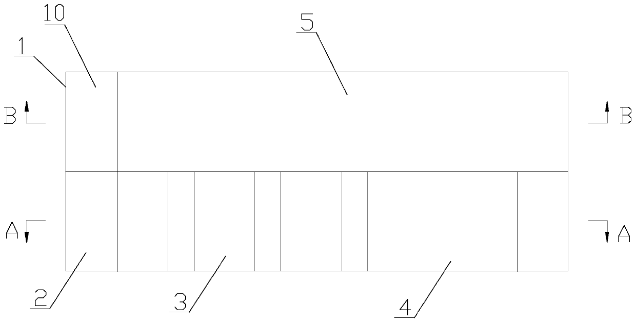
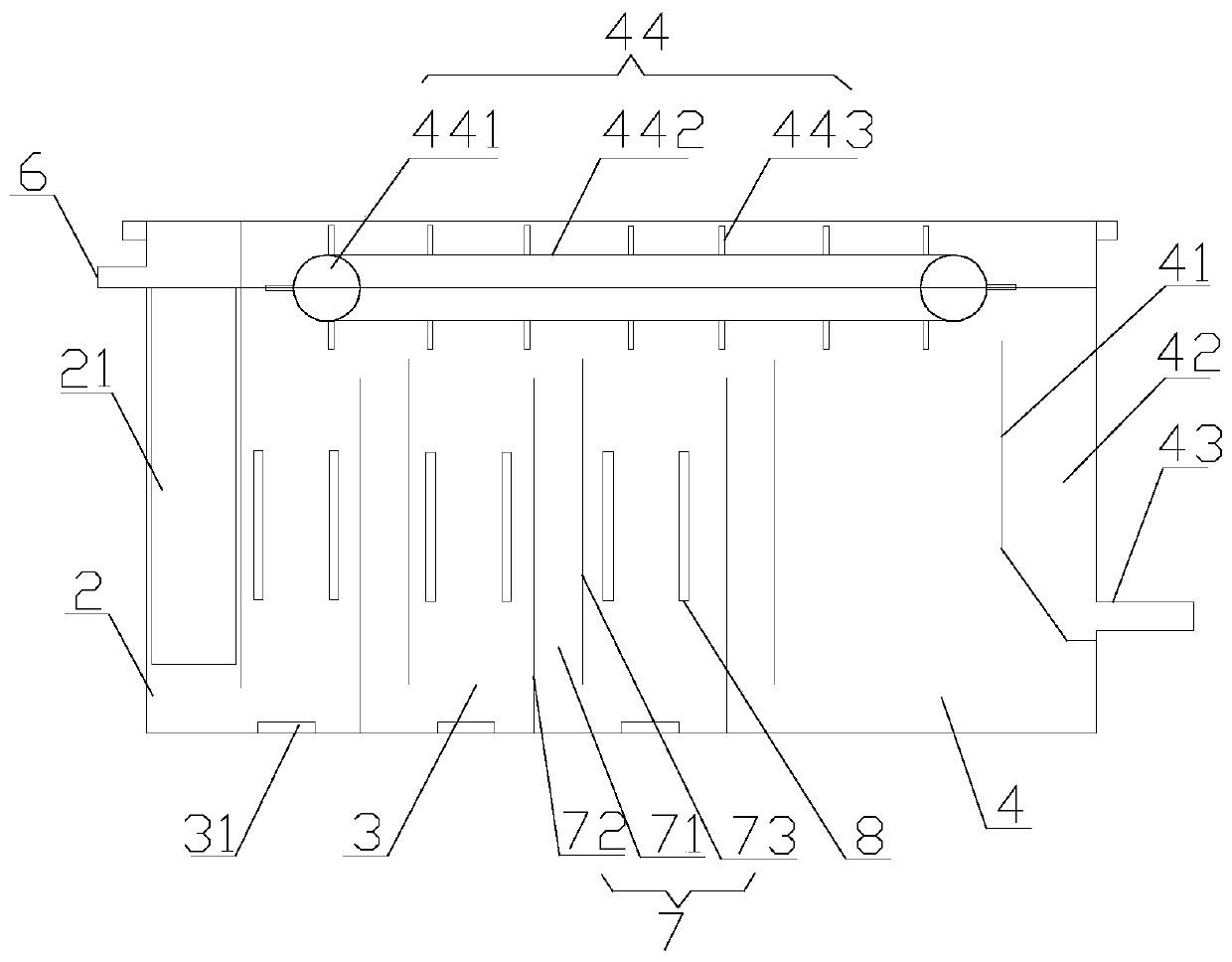
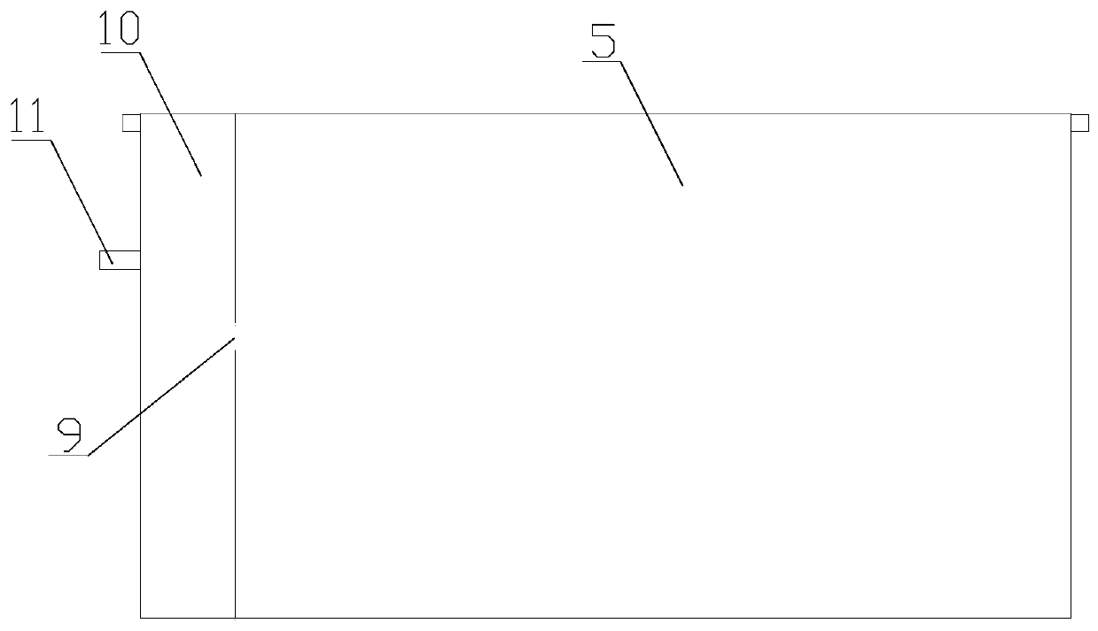
[0040] Such as Figure 1 to Figure 3 As shown, this embodiment provides an electrocoagulation oil-water separator, which includes a box body 1 , and the box body 1 is divided into a filter chamber 2 , an electrolysis chamber 3 , a water purification chamber 4 and a settling chamber 5 by partitions.

[0041] Wherein: the upper part of the filter chamber 2 is provided with a separator water inlet 6, and the bottom of the electrolysis chamber 3 and the filter chamber ...


PUM


Abstract

The invention relates to the field of water treatment, in particular to an electric flocculation oil-water separator. The electric flocculation oil-water separator comprises a box body; the box body is divided into a filter chamber, an electrolysis chamber, a water purification chamber and a settling chamber by partition plates; a separator water inlet is formed in the upper part of the filter chamber; the bottom of the electrolysis chamber is communicated with the bottom of the filter chamber; a plurality of double-layer partition plates are arranged in the filter chamber and divide the filter chamber into a plurality of electrolysis chamber units, and a pair of electrodes is arranged between every pair of electrolysis chamber units; a flow channel is formed between the two partition plates of each double-layer partition plate, and the adjacent electrolysis chamber units are communicated through a corresponding flow channel; the flow channels are vertically distributed, a flow channelwater inlet is formed in the upper end of each flow channel, and a flow channel water outlet is formed in the lower end of the flow channel; the bottoms of the water purification chamber and the electrolysis chamber are communicated; the bottoms of the settling chamber and the water purification chamber are communicated, and a settling chamber water outlet is formed in the upper part of the settling chamber. An S-shaped circulation path is formed in the electrolysis chamber, so that swill can be fully electrolyzed, and the water treatment efficiency is improved.

Description

technical field [0001] The invention relates to the field of water treatment, in particular to an electric flocculation water separator. Background technique [0002] Canteens, restaurants, etc. produce a large amount of kitchen swill every day, which mainly contains oil, water and organic matter. If it is directly discharged into urban sewers without treatment, it will have a great impact on the environment. And it may be collected and refined by unscrupulous traders into "gutter oil" and reused, endangering people's health. [0003] Existing oil-water separation equipment and methods mainly include grease traps, coagulation dosing, and air flotation. The grease trap uses the different density of oil and water in the sewage to achieve the purpose of oil-water separation, but this method occupies a large area, and the oil removal efficiency is low, and the water quality stays in the grease trap for too long, which may easily lead to organic matter corruption , producing an...

Claims


Application Information

Patent Timeline
Patent Type & Authority Applications(China)
IPC IPC(8): C02F9/06
CPCC02F1/001C02F1/40C02F1/463C02F1/52C02F9/00
Inventor 付岩松
Owner 北京丰舜通环保科技有限公司
Why Eureka
Try Eureka