Intelligent sling and hanging method thereof
A sling and intelligent technology, applied in the field of sling, can solve problems such as limited equipment working methods
- Summary
- Abstract
- Description
- Claims
- Application Information
AI Technical Summary
Problems solved by technology
Method used
Image
Examples
Embodiment 1
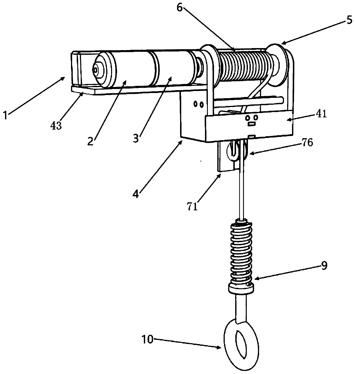
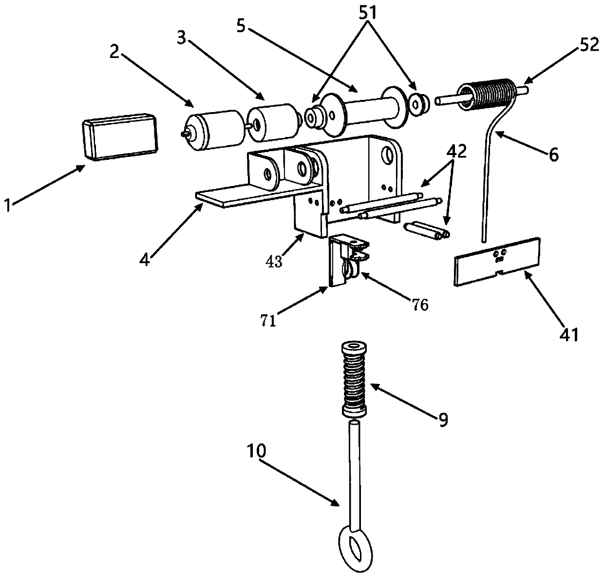
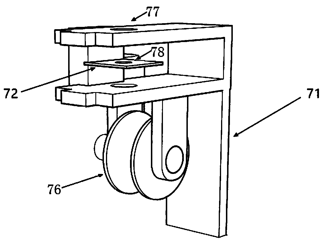
[0060] see Figure 1-4 , the present embodiment provides an intelligent sling, which includes a plurality of sling devices, and each sling device includes a base 4, a sling receiver 5 (also referred to as a winch), a rope 6, a driving device, and a control host 1. The tension gauge 9 and the sling detection system may also include a cover plate 41 , an induction wheel set 42 , a bearing 51 , a fixed shaft 52 and a suspension ring 10 . Of course, in some other embodiments, the cover plate 41 , the induction wheel set 42 , the bearing 51 , the fixed shaft 52 and the suspension ring 10 may not be provided, or only a part of them may be provided. Among them, when the above-mentioned structures need to be connected, they can be connected by buckles, screws, glue, threads and other processes, and all connection structures can be connected by bearings as needed to meet the motion state. At the same time, all electronic equipment will be connected by wires, cables, etc. according to ...
Embodiment 2
[0076] see Figure 5 as well as Image 6, this embodiment provides an intelligent sling, which specifies the structure of the rotational speed measurement module on the basis of Embodiment 1. The rotational speed measurement module includes an encoder code disc 73 and a rotational speed encoder 74 . The encoder code wheel 73 is coaxially arranged and connected to the pulley 76 , and the rotational speed encoder 74 is used to detect the rotational speed of the encoder code wheel 73 . Wherein, the rotation speed of the pulley 76 is the same as that of the encoder code disc 73 . When the rope 6 is lifted and lowered, the rope 6 pulls the pulley 76 to rotate, and then drives the encoder code disc 73 to rotate, and the disc body part of the encoder code disc 73 is arranged in the detection port of the rotational speed encoder 74, and the rotational speed encoder 74 can calculate the unit time The number of turns of the inner encoder code wheel 73 can be used to grasp the rotatio...
Embodiment 3
[0078] see Figure 7-10 , this embodiment provides a smart sling, which adds a wireless charger 7 and a wireless transmission module 8 on the basis of Embodiment 2. Wherein, the wireless transmission module 8 includes a wireless communication module, a wireless charging module and a power supply. The wireless communication module is used for wirelessly transmitting the data detected by the tension gauge 9 and the rotational speed measurement module to the control host 1 . The power supply is used to supply power to the wireless communication module and the rotational speed measurement module, and the wireless charging module is used to charge the power supply. The wireless charger 7 is installed on the bracket 71 and is used to charge the power supply through the wireless charging module.
[0079] In this way, the sling of this embodiment has the ability of wireless charging. When the device recovers all the ropes 6, the wireless charging board at the bottom of the device, t...
PUM
 Abstract
Description
Claims
Application Information
 - R&D Engineer
- R&D Manager
- IP Professional
- Industry Leading Data Capabilities
- Powerful AI technology
- Patent DNA Extraction
Browse by: Latest US Patents, China's latest patents, Technical Efficacy Thesaurus, Application Domain, Technology Topic, Popular Technical Reports.
© 2024 PatSnap. All rights reserved.Legal|Privacy policy|Modern Slavery Act Transparency Statement|Sitemap|About US| Contact US: help@patsnap.com


