
Greenhouse micro-spray irrigation system

A technology for irrigation systems and greenhouses, applied in waterway systems, sewer systems, greenhouse cultivation, etc., can solve problems such as increasing stem and leaf diseases and insect pests, large water consumption for seepage irrigation, and insufficient bottom moisture

Inactive Publication Date: 2020-01-31
SHANDONG SUNWAY LANDSCAPE TECH
View PDF7 Cites 2 Cited by
  • Summary
  • Abstract
  • Description
  • Claims
  • Application Information

AI Technical Summary

Problems solved by technology

[0002] Greenhouse soil irrigation generally includes sprinkler irrigation, micro-sprinkler irrigation, drip irrigation and infiltration irrigation, etc. Each type has its own advantages and disadvantages. When sprinkler irrigation and micro-sprinkler irrigation are used to replenish water for greenhouse plants, some of them will be sprayed to the ground due to the obstruction of the stem. The surface of stems and leaves increases the pests and diseases of stems and leaves, which is not conducive to water saving. At the same time, because sprinkler irrigation and micro-sprinkler irrigation spray water from the upper part, the humidity of the soil surface is high and the bottom layer is insufficient; while the drip irrigation speed is slow and the water consumption of infiltration irrigation is large
So far there is no greenhouse irrigation system that can be fast, economical and avoid the defects of sprinkler irrigation and micro-sprinkler irrigation

Method used


Image

  • Greenhouse micro-spray irrigation system
  • Greenhouse micro-spray irrigation system
  • Greenhouse micro-spray irrigation system

Examples


Embodiment Construction

[0019] The following will clearly and completely describe the technical solutions in the embodiments of the present invention with reference to the accompanying drawings in the embodiments of the present invention. Obviously, the described embodiments are only some, not all, embodiments of the present invention.

[0020] It should be noted that all directional indications (such as up, down, left, right, front, back...) in the embodiments of the present invention are only used to explain the relationship between the components in a certain posture (as shown in the accompanying drawings). Relative positional relationship, movement conditions, etc., if the specific posture changes, the directional indication will also change accordingly.

[0021] In the description of the embodiments, unless otherwise clearly stipulated and limited, the terms "setting", "connecting" and the like should be interpreted in a broad sense. For example, it can be a fixed connection, a detachable connec...


PUM


Abstract

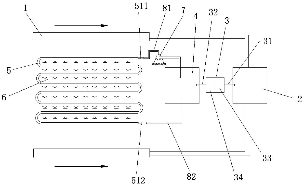
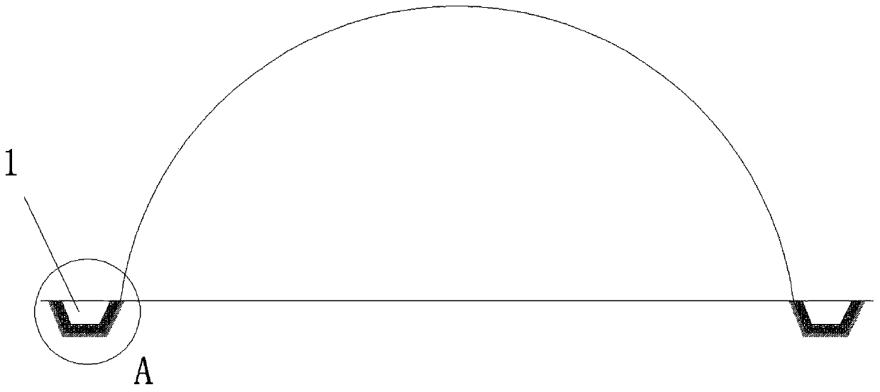
The invention discloses a greenhouse micro-spray irrigation system which comprises stormwater channels on two sides of a greenhouse, a stormwater tank, a water purifier and a micro-spray pipeline. Thestormwater tank is in through connection with the stormwater channels, the water purifier is mounted on one side of the stormwater tank, a water inlet pipe of the water purifier extends into the stormwater tank, a water outlet pipe of the water purifier extends into a water storage tank, the micro-spray pipeline comprises an inner pipe, a hollow outer pipe and a non-woven geotechnical cloth coating layer, gaps are uniformly distributed on the inner pipe, a space between the inner pipe and the hollow outer pipe is filled with sand, the outside of the hollow outer pipe is coated with the non-woven geotechnical cloth coating layer, the micro-spray pipeline is embedded into soil of two sides of a vegetation ridge in the greenhouse, an inlet of the inner pipe is hermetically connected with a pump outlet, a pump inlet extends into the water storage tank, and an outlet of the inner pipe is connected with the water storage tank. According to the irrigation system, soil can be rapidly irrigated through a structure and an embedded position of the micro-spray pipeline, and the system can overcome the shortcomings that water spraying of a common micro-spray pipe is blocked by stems and leaves, diseases and insect pests are increased, surface humidity is high, and bottom humidity is insufficient.

Description

technical field [0001] The invention relates to the field of vegetable greenhouses, in particular to a micro-spray irrigation system for greenhouses. Background technique [0002] Greenhouse soil irrigation generally includes sprinkler irrigation, micro-sprinkler irrigation, drip irrigation and infiltration irrigation, etc. Each type has its own advantages and disadvantages. When sprinkler irrigation and micro-sprinkler irrigation are used to replenish water for greenhouse plants, some of them will be sprayed to the ground due to the obstruction of the stem. The surface of stems and leaves increases the pests and diseases of stems and leaves, which is not conducive to water saving. At the same time, because sprinkler irrigation and micro-sprinkler irrigation spray water from the upper part, the humidity of the soil surface is high, and the bottom layer is not moist enough; while the drip irrigation speed is slow and the water consumption of infiltration irrigation is large. ...

Claims


Application Information

Patent Timeline
Patent Type & Authority Applications(China)
IPC IPC(8): A01G9/24E03F3/04E03F5/10
CPCA01G9/247E03F3/046E03F5/10Y02A40/25
Inventor 王胜李炳文高悦文曹林波江杰
Owner SHANDONG SUNWAY LANDSCAPE TECH
Learn More