
Laser cutting device for noninvasive OLED glass substrate

A glass substrate and laser cutting technology, applied in glass manufacturing equipment, glass cutting devices, manufacturing tools, etc., can solve the problems of difficult adjustment of cutting pressure and depth, high price of high-power laser equipment, and difficulty in multi-photon cutting control. Achieve the effect of good cutting effect, high yield rate and low equipment cost

Inactive Publication Date: 2020-01-24
AENEQ CO LTD
View PDF0 Cites 2 Cited by
  • Summary
  • Abstract
  • Description
  • Claims
  • Application Information

AI Technical Summary

Problems solved by technology

The cutting pressure and depth of the traditional glass knife are not easy to adjust, the compressive strength of the cut glass is not high, the breakage rate is high, and a large number of glass particles are produced; while the water jet cutting has a low processing speed, a large cutting width, and low precision. Water is also not suitable for cutting OLED glass substrate cutting
The more advanced one is to use laser cutting. In laser cutting, if the high-power multi-photon cutting method is used, the cutting effect is relatively better, but high-power laser equipment is expensive, and it is difficult to control multi-photon cutting when cutting large-size glass.

Method used


Image

  • Laser cutting device for noninvasive OLED glass substrate
  • Laser cutting device for noninvasive OLED glass substrate
  • Laser cutting device for noninvasive OLED glass substrate

Examples


Embodiment Construction

[0034] In order to make the technical means, creative features, goals and effects achieved by the present invention easy to understand, the present invention will be further elaborated below in conjunction with illustrations and specific embodiments.

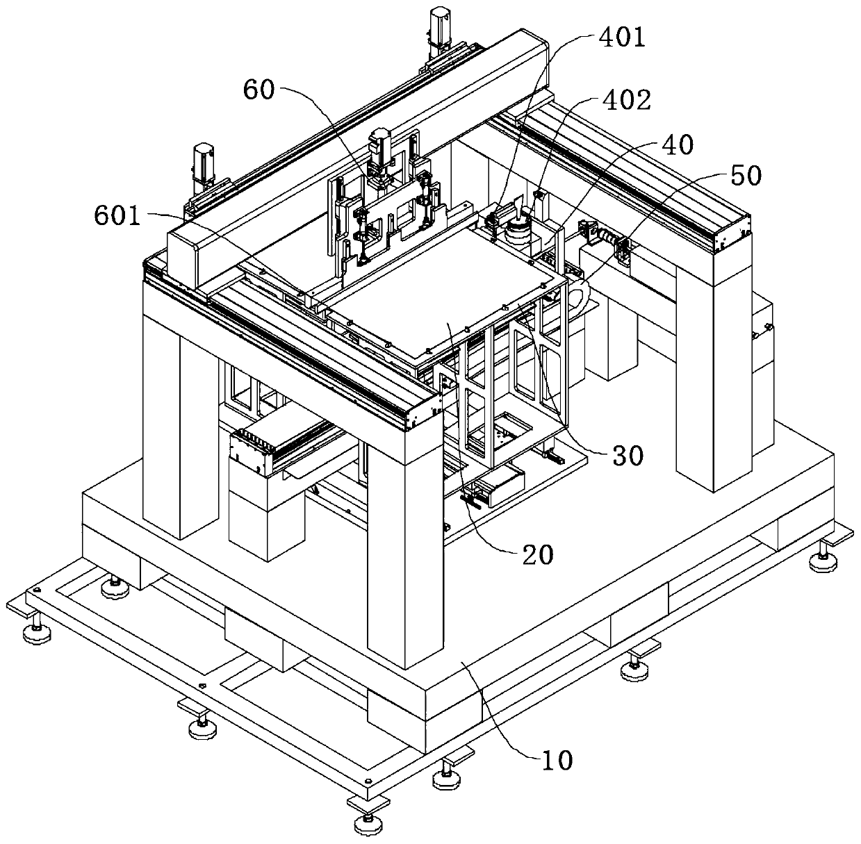
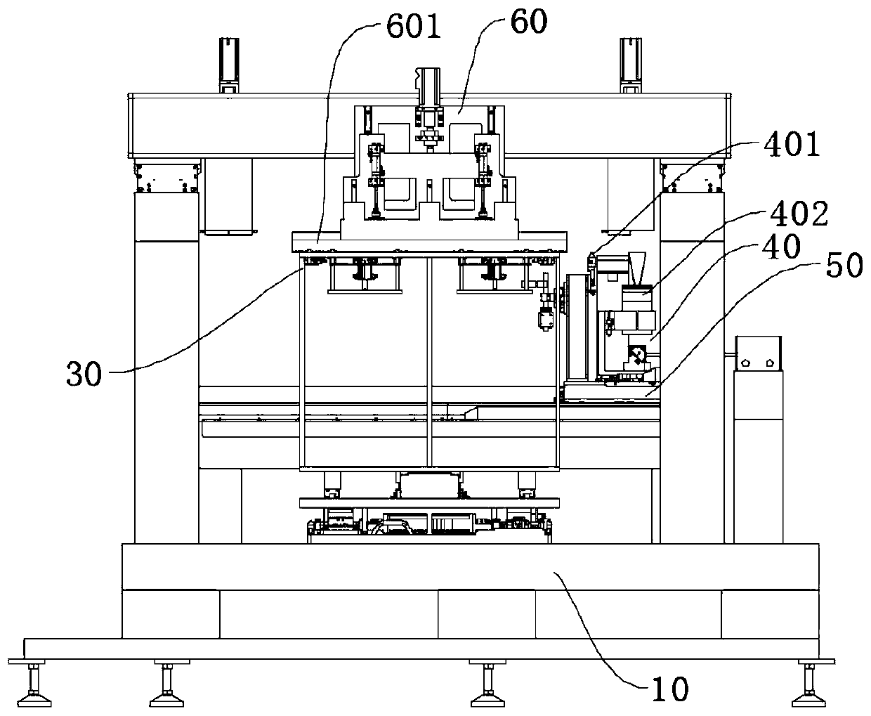
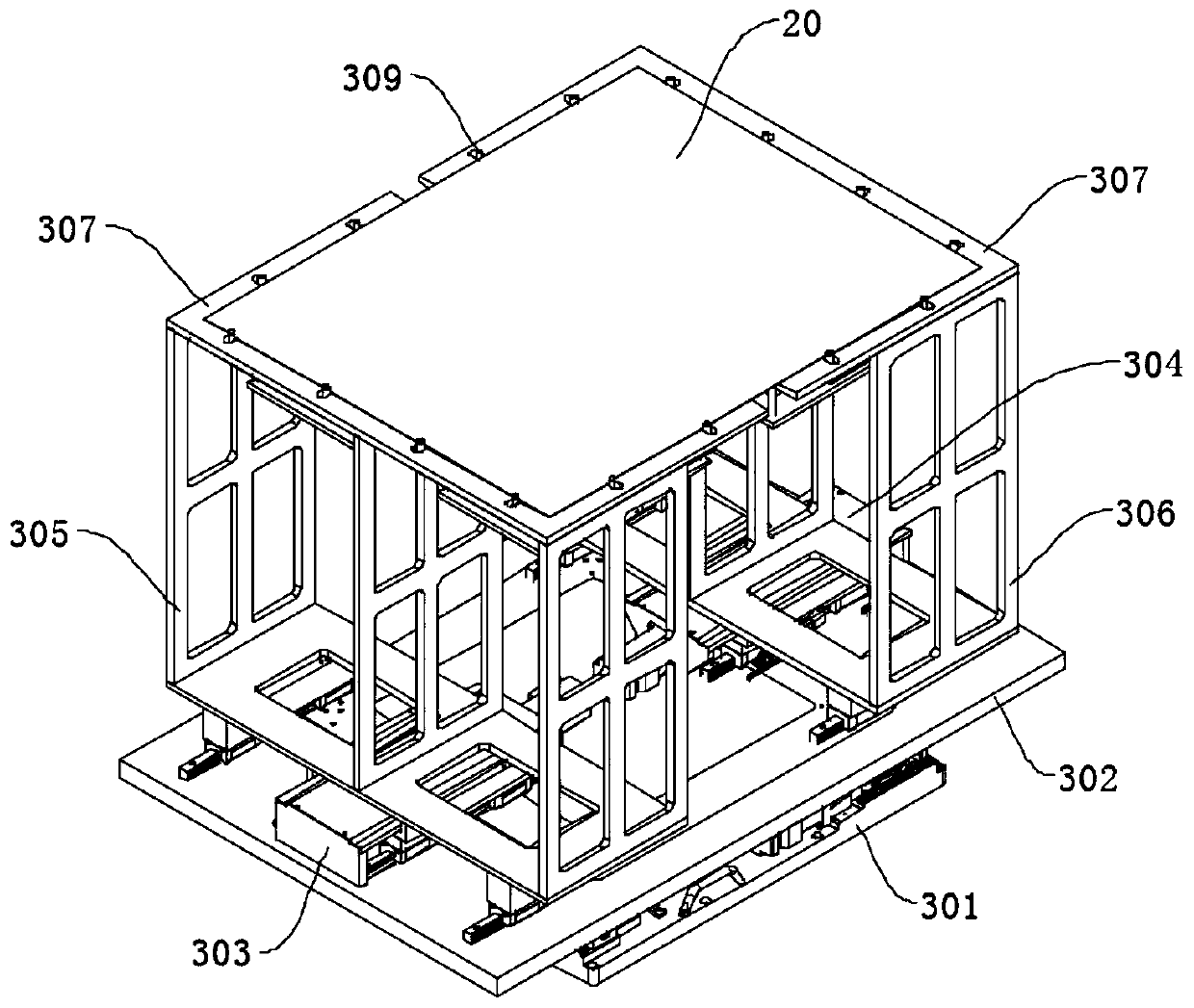
[0035] combine figure 1 and figure 2As shown, a laser cutting device for a non-invasive OLED glass substrate proposed by the present invention includes a stand 10, and the upper end of the stand 10 is provided with a vacuum adsorption workbench 30 for placing the glass substrate 20. Above the stand 10, a A cutting assembly 40 is arranged on the side, and the cutting assembly 40 includes a glass knife 401 for bumping the glass substrate 20 once and a laser lens 402 for cutting the glass substrate 20, and the cutting assembly 40 is fixed on the first X The upper end of the X-axis linear module 50, the first X-axis linear module 50 drives the cutting assembly 40 to pass under the vacuum adsorption workbench 30, and a breaking ass...


PUM


Abstract

The invention relates to the technical field of OLED panel processing, and discloses a laser cutting device for a noninvasive OLED glass substrate. The device comprises a stand, a vacuum adsorption type workbench for storing the glass substrate is arranged at the upper end of the stand, a cutting assembly is arranged on one side of the upper portion of the stand, the cutting assembly comprises a glass cutter used for conducting primary collision on the glass substrate and a laser lens used for cutting the glass substrate, the cutting assembly is fixed to the upper end of a first X-axis linearmodule, the first X-axis linear module drives the cutting assembly to penetrate through the lower portion of the vacuum adsorption type workbench, a breaking assembly is further arranged above the vacuum adsorption type workbench, the breaking assembly comprises a breaking knife arranged in a lifting mode, and the breaking knife is used for separating the cut glass substrate. The glass cutter andthe linear CO2 laser are combined to guide crack type scribing of the glass, and the breaking cutter is matched, so the cutting speed is high, and trimming is not needed after processing is completed.

Description

technical field [0001] The invention relates to the technical field of OLED panel processing, in particular to a laser cutting device for a non-invasive OLED glass substrate. Background technique [0002] In recent years, through its increasingly mature production technology, OLED display screens have successively landed in various mobile phone markets. Because of its high luminous efficiency, short response time, high definition and contrast, nearly 180° viewing angle, wide operating temperature range, flexible display and wide color gamut full-color display, etc., it has occupied the middle and high-end mobile phones of major brands. The display panel market of mobile phone models will have a broader application market in the future. [0003] In the production process of OLED displays for mobile phones, according to the current production process of the factory, the cutting of the glass substrate is an essential process. At present, the production line of the mainstream ...

Claims


Application Information

Patent Timeline
Patent Type & Authority Applications(China)
IPC IPC(8): C03B33/09C03B33/033C03B33/03C03B33/027
CPCC03B33/027C03B33/03C03B33/033C03B33/091
Inventor 赖耀升金渶桓王为新江建志
Owner AENEQ CO LTD
Learn More