A charging interface protection structure and electronic equipment
A technology of protective structure and charging interface, applied in connection, circuit, electrical components and other directions, can solve the problems of inconvenient disassembly of equipment, reduce equipment production efficiency, difficult maintenance, etc., and achieve effective shielding and exposure, effective waterproof and dustproof protection. Effect
- Summary
- Abstract
- Description
- Claims
- Application Information
AI Technical Summary
Problems solved by technology
Method used
Image
Examples
Embodiment 1
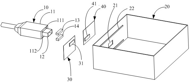
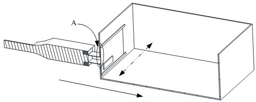
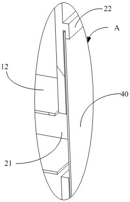
[0025] The protective structure of the charging interface in this embodiment includes a charging plug 10, a housing 20, a first door 30 and a second door 40, the charging plug 10 includes an insertion part 12 and a hand-held part 11, and a magnetic unit is arranged in the hand-held part 11; the housing 20 Specifically, a charging socket 21 for receiving the insertion part 12 is opened on the side wall, and a slide rail 22 is provided on the side wall; a first magnetic part 31 is provided on the first door 30, and a second magnetic part is provided on the second door 40 41. In this embodiment, the first magnetic parts 31 and the second magnetic parts 41 are arranged in parallel and staggered, and the opposite ends of the two are opposite in polarity; when the insertion part 12 is close to the socket 21, the first door 30 and the second door 40 slide along the The rail 22 slides away from the back to expose the socket 21 , and when the insertion portion 12 moves away from the soc...
Embodiment 2
[0038] A magnetic element is arranged on one side (i.e., the upper side or the lower side) of the root of the insertion portion 12 in the handle 11, for example, the magnetic element is the fourth magnetic piece 14 arranged on the lower side of the root of the insertion portion 12, the first The relationship among the magnetic element 31 , the second magnetic element 41 and the fourth magnetic element 14 is the same as that described in the first embodiment above, and will not be repeated here.
Embodiment 3
[0040] Slide rail 22 can be along perpendicular to figure 2 Arranged longitudinally in the dotted line arrow direction, correspondingly, the first magnetic member 31 on the first door 30 and the second magnetic member 41 on the second door 40 are parallel and staggered, and their length direction is the same as that of the first door 30 and the second The opening and closing directions of the door 40 are all perpendicular to figure 2 The direction of the dotted arrow in . Correspondingly, the third magnetic piece 13 and the fourth magnetic piece 14 are arranged on the opposite sides (ie left and right) of the root of the insertion portion 12 in the handle 11, and the first magnetic piece 31, the second magnetic piece 41. The relationship between the third magnetic component 13 and the fourth magnetic component 14 is similar to that described in the first embodiment above, and will not be repeated here.
[0041] It should be noted that the vertically arranged sliding rails ...
PUM
 Abstract
Description
Claims
Application Information
 - R&D
- Intellectual Property
- Life Sciences
- Materials
- Tech Scout
- Unparalleled Data Quality
- Higher Quality Content
- 60% Fewer Hallucinations
Browse by: Latest US Patents, China's latest patents, Technical Efficacy Thesaurus, Application Domain, Technology Topic, Popular Technical Reports.
© 2025 PatSnap. All rights reserved.Legal|Privacy policy|Modern Slavery Act Transparency Statement|Sitemap|About US| Contact US: help@patsnap.com


