Test device and test method for measuring self-loosening of bolts

A test device and self-loosening technology, which is applied in the direction of measuring device, vibration test, mechanical component test, etc., can solve the problem of large difference in stiffness, inability to realize the change of degree of freedom load, and inability to meet the requirements of the anti-loosening performance test of connecting bolts, etc. problem, to achieve the effect of optimizing the anti-loosening design

Active Publication Date: 2020-01-21
SHANGHAI POWER EQUIP RES INST
View PDF7 Cites 3 Cited by
  • Summary
  • Abstract
  • Description
  • Claims
  • Application Information

AI Technical Summary

Problems solved by technology

Existing test devices and methods for bolt looseness testing are still unable to simulate earthquake conditions
The currently used test device for measuring bolt looseness is the lateral vibration test bench for fasteners under lateral load. For example, the test bench built with reference to GB / T 10431-2008 is used to measure the anti-loosening performance of fasteners under lateral vibration. It can apply unidirectional load, but cannot realize load changes in three axial directions and six degrees of freedom, and the test bench cannot realize continuous changes in loading amplitude and frequency. The loading capacity is limited and the loading frequency is low, so it cannot meet the anti-corrosion requirements of connecting bolts under seismic loads. Loose Performance Testing Requirements
In addition, due to the large difference in stiffness between different parts of the equipment, there are often cases where the acceleration response of the connecting bolts at the less rigid part of the equipment under seismic conditions far exceeds the input limit of the seismic test bench, so the bolt loosening test cannot be performed separately test

Method used


Image

  • Test device and test method for measuring self-loosening of bolts

Examples


Embodiment Construction

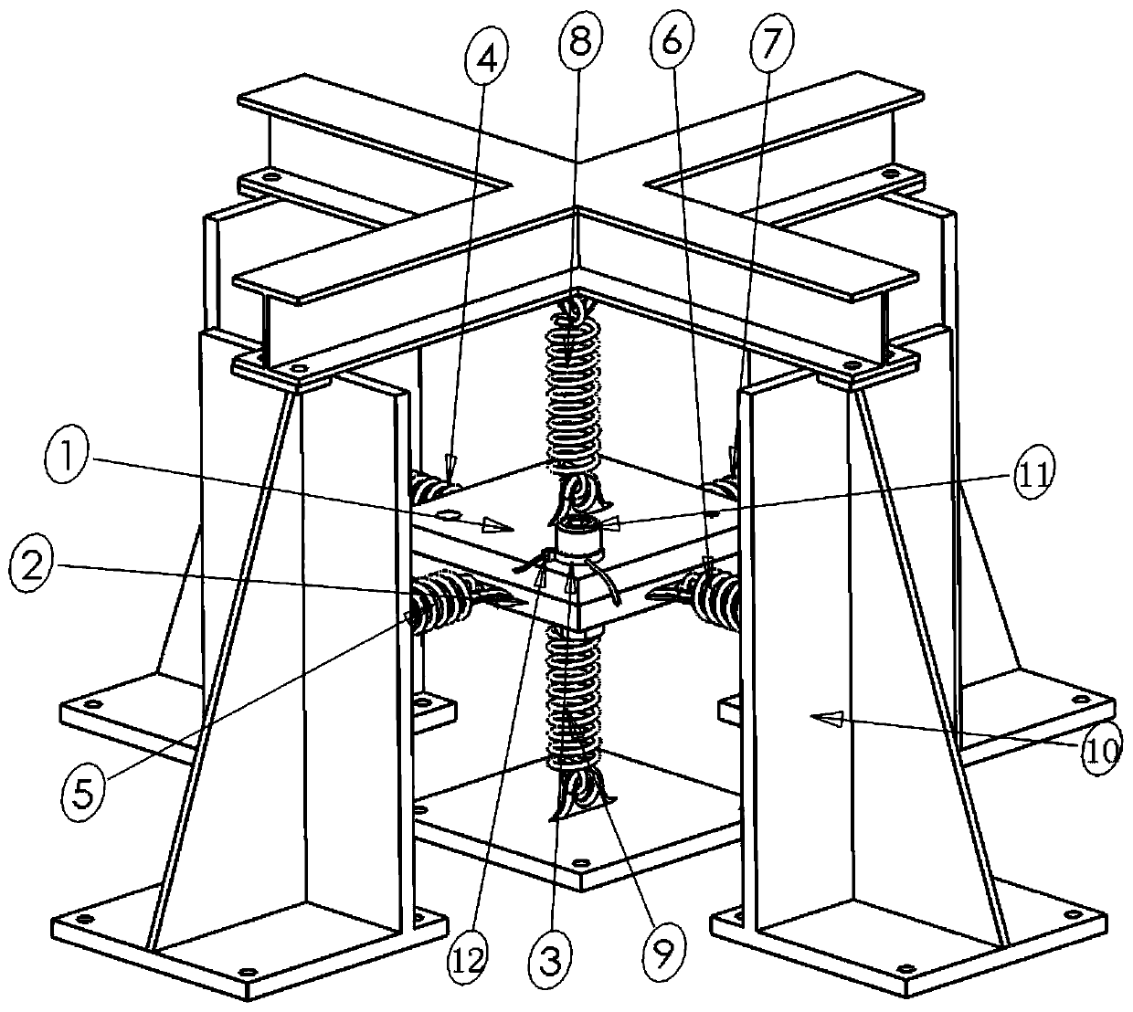
[0021] In order to make the present invention more obvious and understandable, the preferred embodiments are described in detail as follows in conjunction with the accompanying drawings:

[0022] Such as figure 1 As shown, a test device for measuring the self-loosening of bolts includes an outer frame 10, a first clamping plate 1, a second clamping plate 2, a pressure sensor 3, a horizontal spring 4, a horizontal spring 5, a horizontal spring 6, a horizontal Spring 7, vertical spring 8 and vertical spring 9; The outer frame is a cube-shaped steel frame, and six faces of the outer frame form six faces of a cube; The first clamping plate 1 and the second clamping plate are provided in the center of the cube. Two clamping plates 2, the first clamping plate 1 and the second clamping plate 2 are square plate structures; the first clamping plate 1 and the second clamping plate 2 are connected by bolts 11, and the first clamping plate 1 and the second clamping plate 2 are connected b...


PUM


Abstract

The invention relates to a test device and a test method for measuring self-loosening of bolts, and belongs to the technical field of anti-seismic test devices of nuclear power equipment. The test device comprises an outer frame, a first clamping plate, a second clamping plate, a pressure sensor, a horizontal spring and a vertical spring, wherein the first clamping plate, the second clamping plateand the connected spring are combined into a flexible clamp; and the device is used in cooperation with a seismic test table, thereby solving the problem that an existing test device cannot realize continuous change or simultaneous multi-directional loading of the loading amplitude and frequency of a seismic load. The bolts are mounted through the flexible clamp, the clamp is designed according to different response amplification requirements, the acceleration amplification effects of different positions on the nuclear power equipment can be simulated, and then loosening conditions of the bolts at the different positions on the nuclear power equipment can be tested. The device and the method can be used for carrying out bolt connection testing under the seismic load of the nuclear power equipment, and has great significance for optimization and loosening prevention design of the bolts of the nuclear power equipment.

Description

technical field [0001] The invention relates to a test device and a test method for measuring the self-loosening of bolts, belonging to the technical field of anti-seismic tests of nuclear power equipment. Background technique [0002] Bolted connection is the most commonly used structural connection form of nuclear power equipment. Under seismic conditions, the "self-loosening" of bolts is one of the most common failure modes of bolts. Self-loosening means that under certain load conditions, the bolts and nuts rotate relative to each other due to the reduction of self-locking torque, and the pre-tightening force of the bolts is reduced to the point that the bolts lose their normal working performance, or even completely separate. Self-loosening under earthquake conditions will cause failure of the force and movement of the nuclear power equipment structure, seal leakage and other failures, which can cause nuclear power equipment to lose their normal functions, cause major ...

Claims


Application Information

Patent Timeline
IPC IPC(8): G01M13/00G01M7/02
CPCG01M7/02G01M13/00
Inventor 朱幼君丁多亮赵勇
Owner SHANGHAI POWER EQUIP RES INST
Why Eureka
Try Eureka