
A current-carrying friction test method for a double-arm micro-load brush

A current-carrying friction and testing method technology, which is applied in the direction of measuring devices, instruments, and mechanical devices, can solve the problems of small brush wire diameter, inability to clamp, small friction load and friction force, etc., and achieve reliable and fast calculation Easy to install and operate

Active Publication Date: 2021-12-03
贝尔智能装备(南通)有限公司
View PDF6 Cites 0 Cited by
  • Summary
  • Abstract
  • Description
  • Claims
  • Application Information

AI Technical Summary

Problems solved by technology

It can effectively solve the problem that the existing testing machine cannot be clamped due to the small diameter of the brush wire, strong flexibility, small friction load and friction force, and the flexible arm has the function of amplifying the displacement, and can accurately measure the normal load F n , the friction force F can be calculated accurately by measuring the micro-deformation of the brush f

Method used


Image

  • A current-carrying friction test method for a double-arm micro-load brush
  • A current-carrying friction test method for a double-arm micro-load brush
  • A current-carrying friction test method for a double-arm micro-load brush

Examples


Embodiment Construction

[0051] The following examples further illustrate the content of the present invention, but should not be construed as limiting the present invention. Without departing from the essence of the present invention, the modifications and substitutions made to the methods, steps or conditions of the present invention all belong to the scope of the present invention.

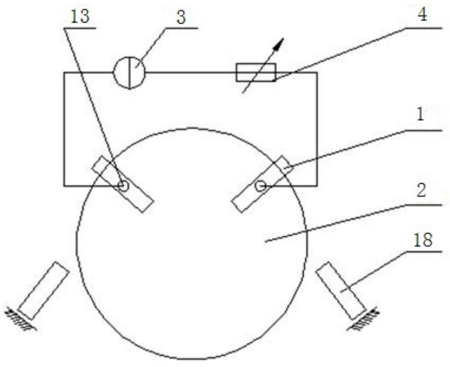
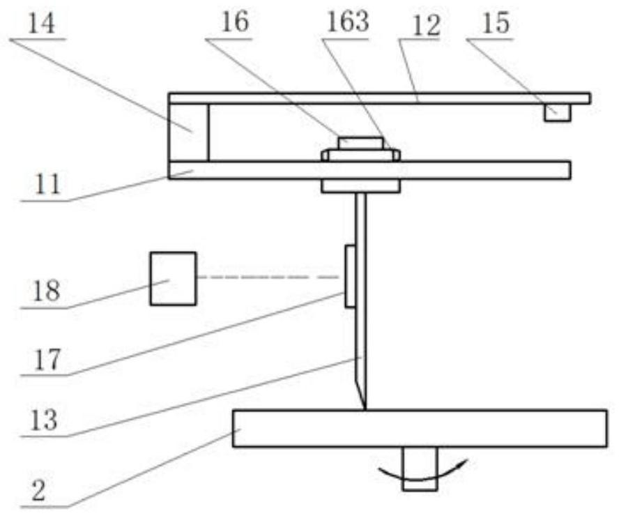
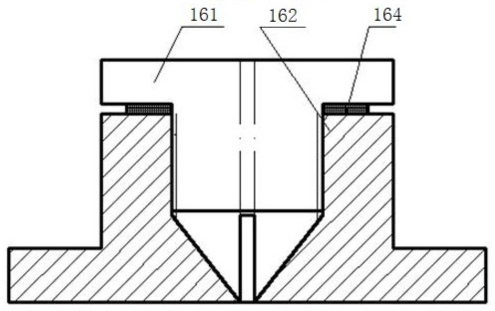
[0052] like Figure 1-3 As shown, the present embodiment provides a dual-arm micro-load brush current-carrying friction test device, which includes two groups of flexible arm assemblies 1, and the flexible arm assembly 1 includes a flexible arm 11, a vertical motion platform 12 and a brush bundle 13. The arm 11 is arranged parallel to the vertical motion platform 12, the axis of the flexible arm 11 projected vertically onto the current-carrying plate 2 passes through the center of the current-carrying plate 2, and the flexible arm 11 is connected to one end of the vertical motion platform 12 through a rigid support 14,...


PUM

PropertyMeasurementUnit
thicknessaaaaaaaaaa
widthaaaaaaaaaa
lengthaaaaaaaaaa

Abstract

The invention discloses a double-arm micro-load brush current-carrying friction test device and a test method. The device includes two groups of flexible arm assemblies. The flexible arm assembly includes a flexible arm, a vertical motion platform and a brush bundle. A capacitive displacement sensor is installed at the position opposite to the free end of the flexible arm. The brush bundle is fixed at the midpoint of the flexible arm and its end is in contact with the current-carrying plate. The brush bundle is provided with a reflector. A laser displacement sensor is arranged at a position corresponding to the reflector in the tangential direction; the constant current source, the brush bundle, the sliding rheostat and the current-carrying plate are connected to form a current loop. Using this device and the corresponding test method to test, effectively solves the problem that the existing testing machine cannot clamp the brush bundle due to the small diameter of the brush wire, strong flexibility, small friction load and friction force, and the flexible arm It has the function of amplifying the displacement and can accurately measure the normal load F n , the friction force F can be calculated accurately by measuring the micro-deformation of the brush bundle f .

Description

technical field [0001] The invention relates to the field of current-carrying friction tests, in particular to a method for testing the current-carrying friction of micro-load brushes. Background technique [0002] The friction pair of brushes and collector rings is used for signal and power transmission between relative rotating parts, and is widely used in wind power generators, camera gimbals, CT machines, etc. When the current passes through the friction interface, due to factors such as contact resistance heat and arc ablation, the temperature of the contact surface continues to rise. This temperature rise phenomenon will cause thermal oxidation on the surface of the material, and the friction coefficient, wear rate, plastic flow and Significant changes in tack were found. The change law and wear mechanism vary with materials, voltage and current, so it is necessary to carry out current-carrying friction experiments of brush wires under different electrical conditions....

Claims


Application Information

Patent Timeline
Patent Type & Authority Patents(China)
IPC IPC(8): G01N19/02
CPCG01N19/02
Inventor 左雪杜梦递周元凯樊玉杰
Owner 贝尔智能装备(南通)有限公司
Learn More