A double-layer continuous pipe threading device and pipe threading method

A pipe threading device and coiled tubing technology, which is applied in the direction of metal processing, metal processing equipment, manufacturing tools, etc., can solve the problems of large impact on the service life of coiled tubing, high manual labor intensity, and large space occupation, so as to reduce labor intensity , easy to operate, small footprint

Active Publication Date: 2020-11-10
SICHUAN HONGHUA PETROLEUM EQUIP
View PDF14 Cites 0 Cited by
  • Summary
  • Abstract
  • Description
  • Claims
  • Application Information

AI Technical Summary

Problems solved by technology

[0002] Double-layer continuous tubing penetration technology is the key to the successful implementation of dual-gradient drilling. Research and implementation of a feasible double-layer continuous tubing penetration technology will make a breakthrough in marine mining equipment. Currently, the penetration technology is mainly divided into vertical suspension There are three types of falling method, horizontal mechanical push-pull method, and horizontal fluid pumping method, and mainly use cables and other soft pipelines. Because the above-mentioned pipe penetration method repeatedly straightens and curls the coiled tubing, it has a great impact on the service life of the coiled tubing, and The manual labor intensity is high, the operation cost is high, and the space occupied during the pipe threading operation is large

Method used


Image

  • A double-layer continuous pipe threading device and pipe threading method
  • A double-layer continuous pipe threading device and pipe threading method
  • A double-layer continuous pipe threading device and pipe threading method

Examples


Embodiment 1

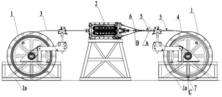
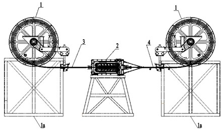
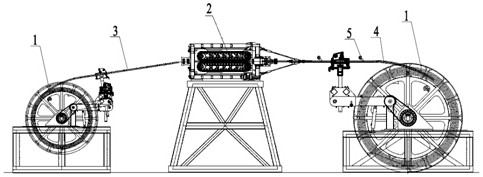
[0047] as attached figure 1 - As shown in 9, a double-layer coiled tubing threading device in this embodiment includes a roller skid 1, an injection head mechanism 2, a coiled tubing 1 3, a coiled tubing 2 4, a water injection device 5, a sealing assembly 6 and a cage 7; Skid 1 includes base 1a, roller 1b, mounting base 1c, power unit 1d, pipe arrangement 1e and depth counter 1f; injection head mechanism 2 includes base 2a, frame body 2b, guide device 2c, gooseneck 2d and push device 2e, the guiding device 2c includes a splint 2c1 and a roller 2c2, the pushing device 2e includes a rotating shaft group 2e1, a chain 2e2 and a clamping block 2f, and a waist-shaped hole 7a is opened on the cage 7; the continuous tube-3 extends through the injection head mechanism 2 After the coiled tubing 1 and the injection head mechanism 2 are installed in place, the coiled tubing 1 3 slides forward under the push of the injection head mechanism 2 to drive the coiled tubing 2. The drum 1b of th...


PUM


Abstract

The invention relates to the technical field of oil exploitation and especially relates to a pipe penetration device and a pipe penetration method for a double-layer continuous pipe. The pipe penetration device comprises two roller pries which are disposed face to face, wherein an injection head mechanism is disposed between the roller pries; one of the roller pries is coiled with a continuous pipe 1; the other roller pry is coiled with a continuous pipe 2; the diameter of the continuous pipe 2 is larger than the diameter of the continuous pipe 1; the continuous pipe 1 passes through the injection head mechanism and extends into the continuous pipe 2; and the injection head mechanism is used for providing power for extension of the continuous pipe 1 into the continuous pipe 2. The device provided by the invention has the beneficial effects that the structure is simple; operations are convenient; the continuous pipe 2 and the continuous pipe 1 are coiled on the two roller pries which are disposed face to face, so occupied space during operations is small; the power is provided by the injection head mechanism, so pipe penetration processes are facilitated, manual labor strength is reduced and operational cost is reduced; and the continuous pipe 1 is pushed by the injection head mechanism to get yield-deformed and slide forwards for pipe penetration, so problems in a conventionalpipe penetration method that a continuous pipe is straightened and curled repeatedly and the service life of the continuous pipe is influenced can be solved.

Description

technical field [0001] The invention relates to the technical field of oil exploitation, in particular to a double-layer continuous pipe threading device and a pipe threading method. Background technique [0002] Double-layer continuous tubing penetration technology is the key to the successful implementation of dual-gradient drilling. Research and implementation of a feasible double-layer continuous tubing penetration technology will make a breakthrough in marine mining equipment. Currently, the penetration technology is mainly divided into vertical suspension There are three types of falling method, horizontal mechanical push-pull method, and horizontal fluid pumping method, and mainly use cables and other soft pipelines. Because the above-mentioned pipe penetration method repeatedly straightens and curls the coiled tubing, it has a great impact on the service life of the coiled tubing, and The manual labor intensity is high, the operation cost is high, and the pipe thread...

Claims


Application Information

Patent Timeline
Patent Type & Authority Patents(China)
IPC IPC(8): B23P19/00
CPCB23P19/00
Inventor 高杭潘田佳俞海明黄秋艳
Owner SICHUAN HONGHUA PETROLEUM EQUIP
Why Eureka
Try Eureka