Electric welding processing equipment for engineering machine parts

A technology for processing equipment and construction machinery, applied in the field of electric welding processing equipment for construction machinery parts, can solve the problems of eye damage, lowering, inconvenient welding efficiency for welding workers, and achieve simple protection tools, improve efficiency, and avoid wire entanglement. Effect

Pending Publication Date: 2020-01-17
XUAZHOU HEIBAILONG ENG NYLON
View PDF0 Cites 0 Cited by
  • Summary
  • Abstract
  • Description
  • Claims
  • Application Information

AI Technical Summary

Problems solved by technology

[0003] Construction machinery parts need to be welded with electric welding machines and other equipment during the welding process. In order to ensure the speed and efficiency of construction machinery parts welding, assembly line welding is usually used to weld mechanical equipment. Welding masks are required during the welding process Eye protection. It is inconvenient to use the welding mask when the transmission welding equipment is in use. The inconvenient access of the welding workers reduces the welding efficiency, which leads some workers to give up using the welding mask directly, which will cause certain damage to the eyes.

Method used


Image

  • Electric welding processing equipment for engineering machine parts
  • Electric welding processing equipment for engineering machine parts
  • Electric welding processing equipment for engineering machine parts

Examples


Embodiment Construction

[0027] In order to make the technical means, creative features, goals and effects achieved by the present invention easy to understand, the present invention will be further described below in conjunction with specific embodiments.

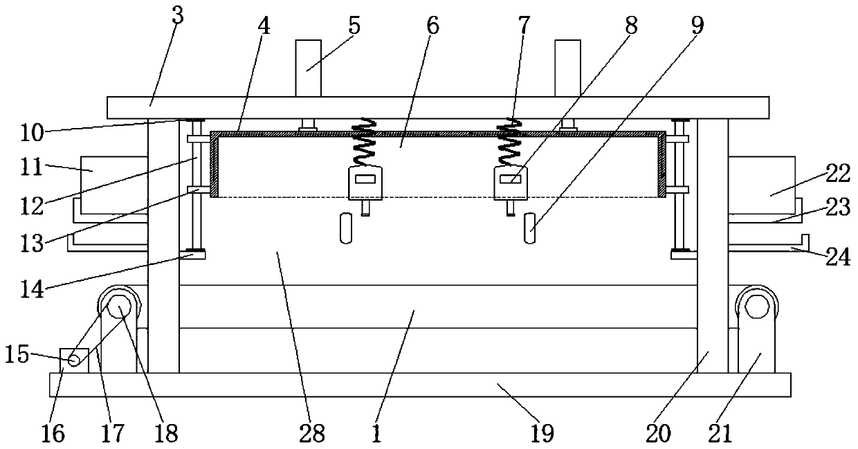
[0028] see Figure 1-5 , the present invention provides a technical solution: an electric welding processing equipment for engineering machinery parts, including a conveyor belt 1 and a control computer 2, the control computer 2 is placed on one side of the conveyor belt 1, and the conveyor belt 1 is supported and fixed on the The upper end of the base 19, the conveyor belt 1 is rotatably fixed on the upper end of the support rod 21 through the transmission shaft 27, the upper end of the base 19 is supported and fixed with a crossbeam 3 by the support beam 20, and the two rear sides of the lower end of the crossbeam 3 The upper end of the base 19 between the support beams 20 is fixed with a rear support plate 28, the inner side of the middle part ...


PUM


Abstract

The invention discloses electric welding processing equipment for engineering machine parts. The electric welding processing equipment includes a conveyor belt and a control computer, the control computer is placed on one side of the conveyor belt, the conveyor belt is supported and fixed at the upper end of the base through support rods, the conveyor belt is rotationally fixed to the upper ends of the support rods through transmission shafts, the upper end of the base supports and is fixedly provided with a cross beam through support beams, a rear support plate is fixed at the position, between the two support beams on the rear side of the lower end of the cross beam, at the upper end of the base, and a bottom plate is fixedly connected to the inner side of the middle portions of the support beams. During welding operation of the electric welding processing equipment, a filter plate is driven by an electric push rod to be blocked on the front side of the conveyor belt, and a gap is reserved below to protect the eyes against strong light; and meanwhile, an operation space is reserved for operation, the lower end of the cross beam is connected and fixedly provided with an electric welding face cover through a plastic spring rope, the electric welding face cover can be conveniently taken and used at any time, a worker can easily use an eye protection tool, and the efficiency of welding work is improved.

Description

technical field [0001] The invention relates to the technical field of mechanical electric welding processing, in particular to an electric welding processing equipment for construction machinery accessories. Background technique [0002] At present, construction machinery is an important part of the equipment industry. All construction machinery equipment is assembled from its basic accessories. In real life, construction machinery accessories are the main lifeblood of construction machinery. First of all, mechanical accessories play a role in construction machinery. Highly effective, machining refers to the process of changing the shape or performance of a workpiece through a mechanical device, and the process can be divided into casting, forging, stamping, welding, machining, assembly and other processes. [0003] Construction machinery parts need to be welded with electric welding machines and other equipment during the welding process. In order to ensure the speed and e...

Claims


Application Information

Patent Timeline
Patent Type & Authority Applications(China)
IPC IPC(8): B23K37/00F21V33/00
CPCB23K37/00F21V33/00
Inventor 时侠标
Owner XUAZHOU HEIBAILONG ENG NYLON
Why Eureka
Try Eureka