Earth screen shunt vector test system based on GPS source table synchronization and application method thereof

A test system and GPS module technology, applied in the direction of measuring electricity, measuring devices, measuring electrical variables, etc., can solve the problem of single-channel measurement workload easily affected by interference, and achieve the goal of reducing test workload and test time Effect

Inactive Publication Date: 2020-01-14
STATE GRID HUNAN ELECTRIC POWER +2
View PDF10 Cites 1 Cited by
  • Summary
  • Abstract
  • Description
  • Claims
  • Application Information

AI Technical Summary

Problems solved by technology

[0016] The technical problem to be solved by the present invention: Aiming at the problems that the existing test system has time delay, is easily affected by interference and has a large single-channel measurement workload, a ground network shunt vector test system based on GPS source table synchronization and its Application method, the ground network shunt vector test system of the present invention is based on the non-master-slave mode of GPS source table synchronization, the shunt vector measurement technology of multi-channel measurement, the present invention uses the GPS second pulse signal to provide the power source with a second pulse edge for each shunt phase The sampling trigger of the quantity and the control trigger of the total test current provide a synchronous signal, and start the acquisition of each phasor at the same time to ensure the accuracy of the shunt vector measurement

Method used


Image

  • Earth screen shunt vector test system based on GPS source table synchronization and application method thereof
  • Earth screen shunt vector test system based on GPS source table synchronization and application method thereof
  • Earth screen shunt vector test system based on GPS source table synchronization and application method thereof

Examples


Embodiment Construction

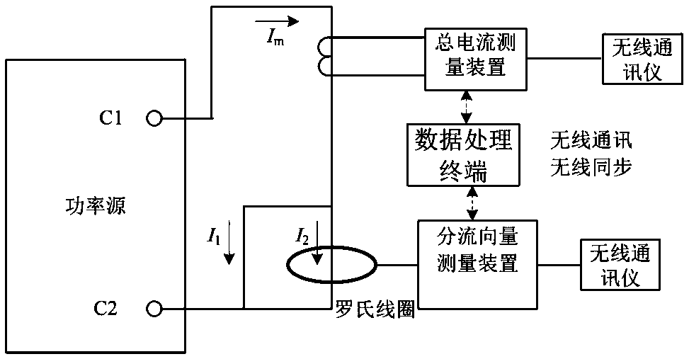
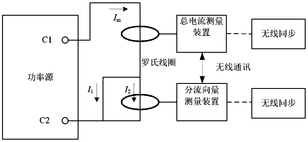
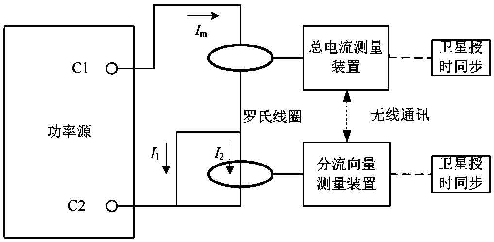
[0038] Such as Figure 4 As shown, the ground network shunt vector test system based on GPS source meter synchronization in this embodiment includes:

[0039] The power source 1 is used to output a constant current source test signal based on the GPS second pulse signal to output a zero-crossing position synchronized with the second pulse edge;

[0040] Shunt vector measurement device 2, used to measure the amplitude of the split vector and the time difference with the second pulse edge based on the second pulse acquisition of the GPS second pulse signal, and determine the different ground shunt vector and constant current source test according to the time difference with the second pulse edge The phase difference between the signals.

[0041] see Figure 4 , this embodiment is based on the ground network shunt vector test system synchronized with the GPS source meter, aiming at the problems that the master-slave working mode of the test system has a delay, is easily affecte...


PUM


Abstract

The invention discloses an earth screen shunt vector test system based on GPS source table synchronization and an application method thereof. According to the invention, a non-master-slave mode is adopted by the earth screen shunt vector test system, a source GPS module is used for providing a pulse per second edge to provide synchronous signals for sampling triggering of each shunt phasor and control triggering of a total test current; each phasor acquisition is started at the same moment and the pulse per second edge is synchronized with the zero crossing point of a constant current source test signal; and the phase of the constant current source test signal is used as the reference phase of each remote shunt vector, and the data acquired by an acquisition channel is used to calculate the time difference based on the pulse per second edge provided by a table GPS module so as to obtain the phase difference relative to the constant current source test signal. According to the invention, source and meter synchronization is achieved, data transmission between the source and the meter is not needed, the test time is greatly reduced, the test efficiency is improved, the multichannel measurement and data acquisition processing technology is adopted, a plurality of shunting points can be tested at the same time, and the test workload is greatly reduced.

Description

technical field [0001] The invention relates to the field of engineering measurement, in particular to a ground network shunt vector test system based on GPS source meter synchronization and its application method, which is used for testing the parameters of the overhead ground wire and the metal frame grounding grounding network of the large-scale ground network lead-in line of the substation Test of shunt effects. Background technique [0002] According to DL / T475-2017 "Guidelines for Measurement of Characteristic Parameters of Grounding Devices", the test of characteristic parameters of large-scale grounding devices should include the following contents: electrical integrity test, ground impedance test (including shunt test), field surface potential gradient distribution test , Measurement of contact potential difference and step potential difference. The above content should be included as far as possible in the characteristic parameter test of other grounding devices. ...

Claims


Application Information

Patent Timeline
IPC IPC(8): G01R31/00G04R20/02
CPCG01R31/00G04R20/02
Inventor 何智强任章鳌李欣胡晓辉
Owner STATE GRID HUNAN ELECTRIC POWER
Why Eureka
Try Eureka