A method and system for measuring the refractive index of particles using the polarization difference of scattered light

A technology of polarization difference and scattered light, applied in measurement devices, particle and sedimentation analysis, particle size analysis, etc., can solve the problem of particle size distribution error, difficult to determine the accurate refractive index of particles, etc., and achieve the effect of accurate sample particle size distribution

Active Publication Date: 2021-09-24
LINKOPTIK INSTR CO LTD
View PDF15 Cites 0 Cited by
  • Summary
  • Abstract
  • Description
  • Claims
  • Application Information

AI Technical Summary

Problems solved by technology

However, the refractive index of the actual sample is related to factors such as the wavelength of the incident light and the content of impurities, so it is difficult to determine the exact refractive index of the particles, which often leads to a large error between the measurement results of the sample and the actual particle size distribution
[0005] So far, although there have been several methods for measuring the refractive index using scattered light signals, all of them have limitations of one kind or another

Method used


Image

  • A method and system for measuring the refractive index of particles using the polarization difference of scattered light
  • A method and system for measuring the refractive index of particles using the polarization difference of scattered light
  • A method and system for measuring the refractive index of particles using the polarization difference of scattered light

Examples


Embodiment Construction

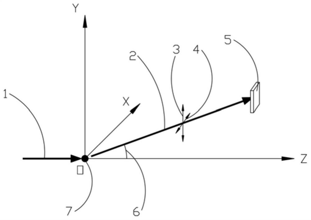
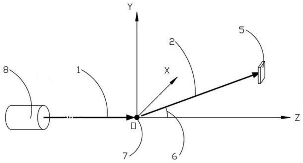
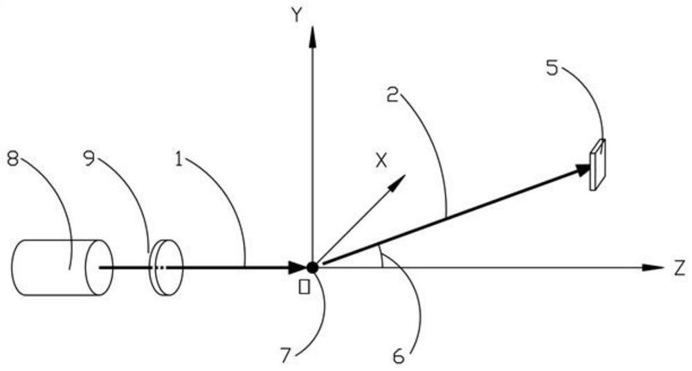
[0023] A method for measuring the refractive index of particles using the difference in polarization of scattered light, comprising the steps of:

[0024] S1, when the light wave is irradiated to the particle located at the coordinate origin O along the Z axis, the light scattered by the particle is received by the detector located on the XOZ plane. The detector is an array composed of multiple independent detection units, all units are located in the XOZ plane, and each unit corresponds to a different scattering angle. Let the total number of detection units be k. When the illumination light is linearly polarized light and the polarization direction is parallel to the Y axis, the polarization directions of the scattered light received by each detection unit are all perpendicular to the XOZ plane, that is, the scattering surface. Sorting from the inside to the outside according to the size of the scattering angle, record the light energy received by each detection unit as E ...


PUM


Abstract

The invention discloses a method and system for measuring the refractive index of particles by using the polarization difference of scattered light, the method includes obtaining the vertically polarized scattered light energy distribution E ⊥ and horizontally polarized scattered light energy distribution E || , calculate the scattered light energy distribution polarization difference E d ;According to Mie theory, calculate a set refractive index value n (i) Calculate the particle size distribution W (i) , to obtain the polarization difference of scattered light and calculate E d mean square error σ of (i) , change the value of the refractive index, repeat the above process, and obtain the refractive index with the smallest mean square error, which is the real refractive index of the particle. The particle size distribution calculated using this refractive index is the real particle size distribution of the particle. A method for realizing the above is also provided In the present invention, when the refractive index and particle size distribution of the measured particle sample are unknown, the scattered light signal itself obtained by the laser particle size analyzer can be used to calculate the refractive index of the sample, and then obtain an accurate sample particle size distribution.

Description

technical field [0001] The invention relates to the technical field of particle characterization, in particular to a method and system for measuring the refractive index of particles by using the polarization difference of scattered light. Background technique [0002] Particles refer to geometric bodies with a specific shape generally between millimeters and nanometers in size. Particles not only refer to solid particles, but also fluid particles such as mist droplets and bubbles. Particles are ubiquitous in nature and widely affect or apply to industrial production and scientific research. Particle size is one of the most important parameters of particles. In recent years, the application of various new granular materials has higher requirements for particle size measurement. Laser particle size analyzers based on the principle of static light scattering have been used more and more widely. [0003] According to the geometrical optics approximation theory of light scatt...

Claims


Application Information

Patent Timeline
Patent Type & Authority Patents(China)
IPC IPC(8): G01N15/02
CPCG01N15/0211
Inventor 张晨雨张福根
Owner LINKOPTIK INSTR CO LTD
Why Eureka
Try Eureka