Bridge type direct-view circumcision stitching instrument

A suturing device and foreskin technology, which is applied in medical science, surgical fixation nails, surgery, etc., can solve the problems of inability to precisely control the cutting length, inconvenient removal of the nail body, secondary injury to patients, etc., so as to avoid medical accidents and secondary injuries. surgery, reducing the pain of surgery and dressing changes, reducing the effect of injury

Inactive Publication Date: 2020-01-14
李锦恒
View PDF1 Cites 0 Cited by
  • Summary
  • Abstract
  • Description
  • Claims
  • Application Information

AI Technical Summary

Problems solved by technology

In this patent, the glans cover is covered and the foreskin is pulled out to the inside of the device, and then fixed, cut and sutured. During the cutting process, the glans and the foreskin at the cut site are covered by the nail anvil assembly and the staple cartridge sleeve, and the surgical field of view is completely blocked. It is not conducive to the operation, and at the same time, the length of the cut cannot be precisely controlled, and may cause secondary damage to the patient
In addition, the nail body is directly nailed to the body tissue, and it is easy to be wrapped by the body tissue when the wound heals. It is very inconvenient to disassemble the nail body, and it is easy to cause secondary injury

Method used


Image

  • Bridge type direct-view circumcision stitching instrument
  • Bridge type direct-view circumcision stitching instrument
  • Bridge type direct-view circumcision stitching instrument

Examples


Embodiment 1

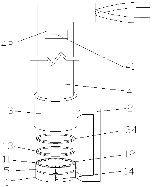
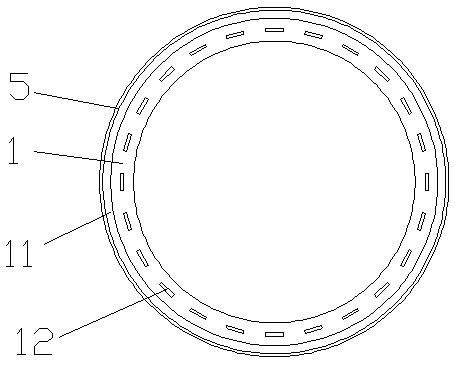
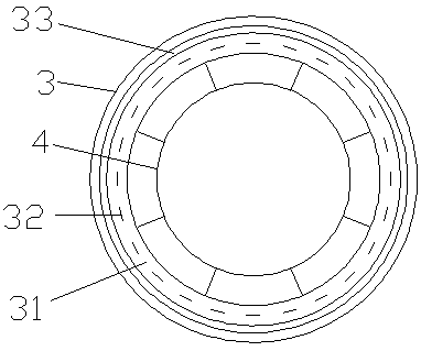
[0032] The cross-section of the nail drill ring seat 1 is circular, which is convenient for cutting and suturing. Preferably, the diameter of the nail-drill ring seat 1 is 2-4cm, which is suitable for circumcision of patients of different ages. Correspondingly, the movable part 31, the lower hemostatic membrane 13 and the upper hemostatic membrane 34 all adopt a circular structure that matches the nail drill ring seat 1, so that it can be matched with the nail drill ring seat 1 and the nail cartridge assembly 3 Install.

Embodiment 2

[0034] The cross-section of the nail drill ring seat 1 is elliptical, which is convenient for cutting and suturing. Preferably, the minor axis length of the nail drill ring seat 1 is 2-4cm, which is suitable for circumcision of patients of different ages. axis length. Correspondingly, the movable part 31, the lower hemostatic film 13 and the upper hemostatic film 34 all adopt an elliptical ring structure that matches the nail drill ring seat 1, so that it can be matched and installed with the nail drill ring seat 1 and the nail cartridge assembly 3 .

[0035]The cross-section of the nail drill ring seat 1 can also be designed into other structures such as a quasi-elliptical ring, so that it can be convenient for eversion and fixing of the foreskin edge. The surgical steps for circumcision using the bridge-type direct vision circumcision stapler of the present invention are as follows: according to the needs of the operation, the nail drill ring seat 1 of appropriate size and...


PUM


Abstract

The invention discloses a bridge type direct-view circumcision stitching instrument, which comprises a nail drill ring base (1), a bridge type fixing frame (2), a nail bin assembly (3), a pressurizinghandle (4) and a fixing piece (5). Wherein the nail drill ring base (1) is of a hollow annular columnar structure, and an annular cutting surface (11) and a plurality of annularly arranged nail bodygrooves (12) are arranged on the nail drill ring base; the glans penis penetrates through the nail drill ring base from bottom, and the prepuce turn out and wraps the nail drill ring base through a fixing piece, the bridge type fixing frame is connected with the nail drill ring base and the nail bin assembly, movable parts (31) are arranged in the nail bin assembly, the nail bodies (32) corresponding to the nail body grooves one to one are arranged in the movable parts, and annular cutting blades (33) are arranged at the bottoms of the movable parts; and a pressurizing handle is arranged on the nail bin assembly and is connected with and controls the movable part. According to the instrument, the circumcision process can be visualized, the prepuce cutting length can be accurately controlled, the safety and operability of a circumcision operation are improved, and postoperative recovery is facilitated.

Description

technical field [0001] The invention relates to a circumcision surgical tool, in particular to a bridge-type direct vision circumcision stapler. Background technique [0002] Excessive prepuce or phimosis may lead to various inflammations, infections, poor urination and other problems, and even induce malignant tumors of the penis, seriously affecting the health and life of men. Surgical removal of the overlong foreskin can avoid the above-mentioned problems. the occurrence of disease. Circumcision surgery does less harm to the patient, and the postoperative recovery is also faster. The circumcision stapler of the prior art can cut and suture the foreskin once, with short operation time and fewer bleeding points. main tool. [0003] Chinese invention patent ZL201510442478.4 discloses a foreskin cutting and suturing device, which includes an abutment seat assembly, suturing staples set in the staple cartridge, a staple cartridge cover, a force device connected to the staple...

Claims


Application Information

Patent Timeline
Patent Type & Authority Applications(China)
IPC IPC(8): A61B17/326A61B17/115A61B17/12A61B90/00
CPCA61B17/1155A61B17/12A61B17/326A61B90/06A61B2017/12004A61B2090/061
Inventor 李锦恒
Owner 李锦恒
Why Eureka
Try Eureka