
Streak tube imaging lidar distance strobing gate control method and device

A technology of laser radar and control method, which is applied in the field of radar detection, can solve problems such as ungiven technical solutions, and achieve the effect of simple structure, accurate detection results and wide application

Inactive Publication Date: 2020-01-10
HUNAN GUOTIAN ELECTRONICS TECH CO LTD
View PDF8 Cites 5 Cited by
  • Summary
  • Abstract
  • Description
  • Claims
  • Application Information

AI Technical Summary

Problems solved by technology

Visible, this prior patent application also does not provide the technical scheme that solves the above-mentioned technical problem

Method used


Image

  • Streak tube imaging lidar distance strobing gate control method and device
  • Streak tube imaging lidar distance strobing gate control method and device

Examples


Embodiment Construction

[0012] In order to make the object, technical solution and advantages of the present invention clearer, the present invention will be described in further detail below in conjunction with the embodiments and accompanying drawings. Here, the exemplary embodiments and descriptions of the present invention are used to explain the present invention, but not to limit the present invention.

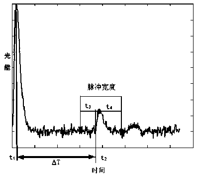
[0013] An embodiment of the present invention provides a method for controlling a range gate of a striped tube lidar, such as figure 1 shown, including the following:

[0014] Detect laser emission time t 1 ;

[0015] Detect the moment t when the reflected light signal is received 2 ;

[0016] The round-trip time is determined according to the moment of laser emission and the moment of receiving the reflected light signal. The formula for calculating the round-trip time ΔT is: ΔT=t 2 -t 1 ;

[0017] According to the laser emission time, the round-trip time and the preset distance gate op...


PUM


Abstract

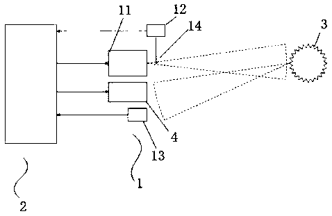
The invention relates to a streak tube imaging lidar distance strobing gate control method. The method comprises the following steps that: a laser emission moment is detected; a reflected light signalreceiving moment is detected; round-trip time is determined according to the laser emission moment and the reflected light signal receiving moment; the opening time of a distance strobing gate is determined according to the laser emission moment, the round-trip time and the preset time advance quantity of the opening of the distance strobing gate; and the closing time of the distance strobing gate is determined according to the laser emission moment, the round-trip time and the preset time delay quantity of the closing of the distance strobing gate. The invention also relates to a streak tubeimaging lidar distance strobing gate control device. According to the streak tube imaging lidar distance strobing gate control method and device of the invention, the opening time and closing of thedistance strobing gate can be automatically determined under the condition that a target distance is uncertain.

Description

technical field [0001] The invention relates to the technical field of radar detection, in particular to a control method and device for a range gate of a stripe tube laser radar. Background technique [0002] Range-gated striped tube lidar has unique advantages in the field of detection, especially in the field of underwater detection. Its range resolution is high, and the mechanism of range gating can effectively reduce the influence of water body backscatter on measurement results. However, in practical applications, it is found that under the condition of uncertain target distance, the stripe tube lidar cannot determine the time when the range gate is opened, which will cause the stripe tube lidar to be unable to receive the light signal reflected by the target, due to the distance The opening time of the gate cannot be determined, which indirectly leads to the indeterminability of the closing time of the distance gate. Obviously, the excellent technical advantages of th...

Claims


Application Information

Patent Timeline
Patent Type & Authority Applications(China)
IPC IPC(8): G01S7/483G01S17/88
CPCG01S7/483G01S17/88
Inventor 江峦陈路尤蓉蓉易先林肖志伟吕冰冰
Owner HUNAN GUOTIAN ELECTRONICS TECH CO LTD
Learn More