


Quick Research
Generate reliable direction feasibility study reports for your R&D in just a few steps.

Technical Q&A
Discover and master advanced knowledge NOW. Basics, ideas, possibilities, all at once.

Find Solutions
As an expert in R&D theories, this can generate solutions to your technical problems instantly.

Evaluate Feasibility
Analyze your overall solution with one click, know your potential R&D risks in advance.

Monitor Landscape
Get weekly tech updates, stay abreast of the latest tech innovations and key insights.
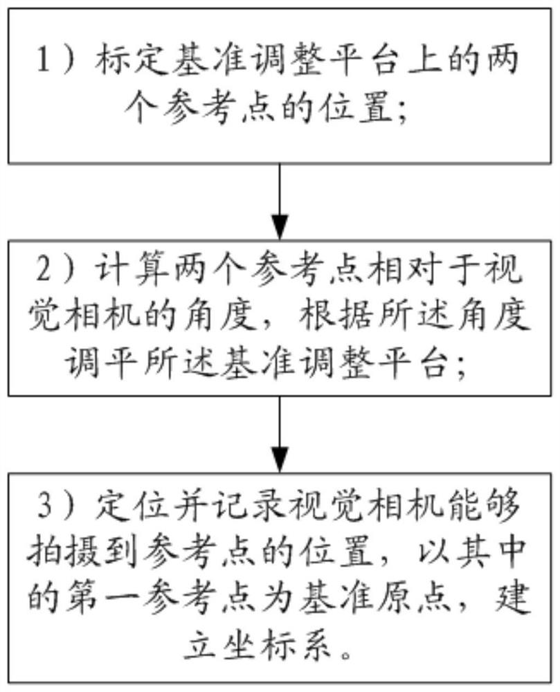
Datum positioning, object attitude adjustment and graphic display method based on machine vision
A positioning method and machine vision technology, applied in instruments, measuring devices, optical devices, etc., can solve the problems of poor human-computer interaction, no graphical interaction, and inability to know the true posture of the detected object, so as to shorten the time for positioning compensation. , the effect of shortening the positioning time
- Summary
- Abstract
- Description
- Claims
- Application Information
AI Technical Summary
Problems solved by technology
Method used
Image

Examples
specific Embodiment approach
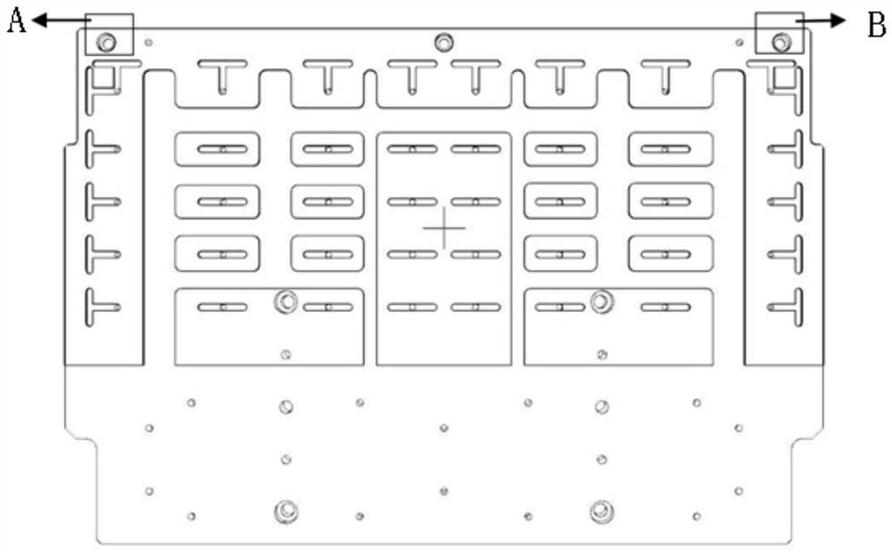
[0066] figure 2 A schematic diagram of a fiducial adjustment platform for realizing the fiducial positioning method based on machine vision according to the present invention is schematically represented. Such as figure 2 As shown, there are two calibration holes A and B on the benchmark adjustment platform, which are regarded as two reference points. The benchmark adjustment platform can be installed on any combination of kinematic mechanisms as required.
[0067] In this embodiment, first, move the visual camera so that the benchmark adjustment platform reference point A is within the camera field of view, and record the position of the current axis (the position of the axis is the position that can prompt the visual camera to take pictures of the reference point A in the present invention, This position is not a fixed point, but refers to various points within the range where the reference point A can be photographed).
[0068] Second, move the visual camera so that th...
PUM
 Abstract
Description
Claims
Application Information
 - R&D Engineer
- R&D Manager
- IP Professional
- Industry Leading Data Capabilities
- Powerful AI technology
- Patent DNA Extraction
Browse by: Latest US Patents, China's latest patents, Technical Efficacy Thesaurus, Application Domain, Technology Topic, Popular Technical Reports.
© 2024 PatSnap. All rights reserved.Legal|Privacy policy|Modern Slavery Act Transparency Statement|Sitemap|About US| Contact US: help@patsnap.com