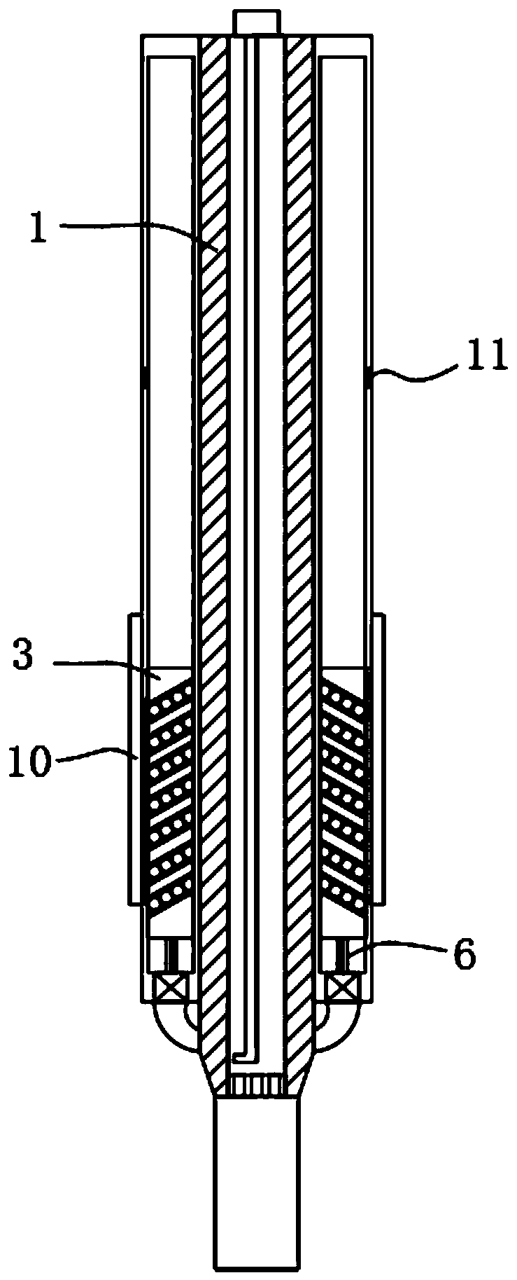
Shaping pipe for glass manufacturing

A glass manufacturing and shaping technology, which is applied in the field of shaping tubes for glass manufacturing, can solve problems such as dizziness of producers, reduce work efficiency, and increase burden on producers, and achieve the effects of reducing burden, increasing efficiency, and high precision

Inactive Publication Date: 2020-01-10
林佳铭
View PDF0 Cites 1 Cited by
  • Summary
  • Abstract
  • Description
  • Claims
  • Application Information

AI Technical Summary

Problems solved by technology

[0003] In many glass shaping processes, it is necessary to rely on manpower to blow the molten glass with a steel pipe and then shape the molten glass, which greatly increases the burden on the producer and easily makes the producer dizzy due to lack of oxygen in the brain. while reducing work efficiency

Method used


Image

  • Shaping pipe for glass manufacturing
  • Shaping pipe for glass manufacturing

Examples


Embodiment Construction

[0017] The following will clearly and completely describe the technical solutions in the embodiments of the present invention with reference to the accompanying drawings in the embodiments of the present invention. Obviously, the described embodiments are only some, not all, embodiments of the present invention.

[0018] In describing the present invention, it should be understood that the terms "center", "longitudinal", "transverse", "length", "width", "thickness", "upper", "lower", "front", " Orientation or position indicated by "back", "left", "right", "vertical", "horizontal", "top", "bottom", "inner", "outer", "clockwise", "counterclockwise", etc. The relationship is based on the orientation or positional relationship shown in the drawings, and is only for the convenience of describing the present invention and simplifying the description, rather than indicating or implying that the referred device or element must have a specific orientation, be constructed and operated in...


PUM


Abstract

The invention discloses a shaping pipe for glass manufacturing. The shaping pipe comprises a steel pipe, a vertically arranged mounting cavity is formed in the steel pipe, a flow limiting plate is mounted in the mounting cavity, the upper end of the flow limiting plate is in threaded connection with a dial, the dial is rotatably connected to the upper end of the steel pipe, a flow distribution plate is fixedly connected to the bottom end of the mounting cavity, a plurality of through holes are formed in the flow distribution plate at equal intervals, a mounting sleeve is further mounted on thesteel pipe, vertically-arranged cavities are symmetrically formed in the mounting sleeve, and spiral grooves are formed in the inner walls of the cavities. The interaction of structures such as a rotary compression block, the cavities and a flexible connecting pipe is utilized to make a gas evenly move downwards and enter molten glass, so that the molten glass is shaped, thereby faint caused by cerebral hypoxia due to artificial blowing using the shaping pipe is avoided, the burden of a user is reduced, and the manufacturing efficiency is improved.

Description

technical field [0001] The invention relates to the technical field of glass production, in particular to a plastic tube for glass production. Background technique [0002] When glass was used as an industrial material, it quickly occupied the material market share, resulting in the birth of a large number of products produced by glass. It is not only used in industry, but also in decorative glass and aerospace manufacturing. [0003] In many glass shaping processes, it is necessary to rely on manpower to blow the molten glass with steel pipes and then shape the molten glass, which greatly increases the burden on the producer and easily makes the producer dizzy due to lack of oxygen in the brain. Reduced work efficiency simultaneously. Contents of the invention [0004] The purpose of the present invention is to solve the shortcomings in the prior art, such as: in the process of many glass molding, it is necessary to rely on manpower to blow air with steel pipes and then ...

Claims


Application Information

Patent Timeline
IPC IPC(8): C03B9/36
CPCC03B9/3681
Inventor 林佳铭
Owner 林佳铭
Why Eureka
Try Eureka