A new ultra-thin terminal lead for laminated components

A technology of laminated components and left-end leads, which is applied in the field of solar cell components, can solve the problems of increasing the cost of laminated components, low stamping efficiency, and slow speed, and achieve the effects of improving market competitiveness, improving stamping efficiency, and reducing material costs

Active Publication Date: 2021-07-20
LIANYUNGANG SHENZHOU NEW ENERGY
View PDF6 Cites 0 Cited by
  • Summary
  • Abstract
  • Description
  • Claims
  • Application Information

AI Technical Summary

Problems solved by technology

[0006] (1) There are many residual materials after stamping, and there is no way to effectively recycle the residual materials. The cost of the ultra-thin bus bar itself is high, and the large stamping residual materials will further increase the cost of ultra-thin terminal leads and increase the cost of laminated components
[0007] (2) At present, the lead at the end of the laminate needs to be formed by stamping with an ultra-thin substrate. Only one end lead can be produced by one stamping, and the speed is relatively slow
[0013] (3) Only one terminal lead is formed in one stamping, the stamping efficiency is low and there are more stamping residues

Method used


Image

  • A new ultra-thin terminal lead for laminated components
  • A new ultra-thin terminal lead for laminated components
  • A new ultra-thin terminal lead for laminated components

Examples


Embodiment Construction

[0033] The present invention will be further explained below in conjunction with the accompanying drawings and specific embodiments. It should be understood that the following specific embodiments are only used to illustrate the present invention and are not intended to limit the scope of the present invention.

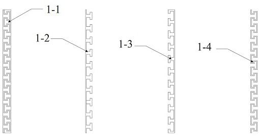
[0034] figure 1 It is the stamping design drawing of the ultra-thin end leads used in the lamination used in the embodiment, and the left end leads 1-2, the right end leads 1-3 and the stamping residue 1-4 are densely arranged on the ultra-thin substrate 1-1. In embodiment 1, the ultra-thin substrate 1-1 has a length of 150mm and a width of 10mm; after stamping, the left and right end leads 1-2 and 1-3 are 150mm long and 8mm wide; , the total length of the residual material is 290mm, and the proportion of the residual material to the substrate is 19.3%.

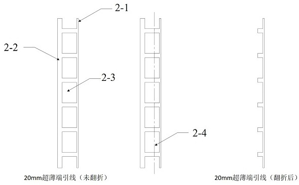
[0035] figure 2 It is the currently commonly used 20mm wide ultra-thin end lead stamping pattern. The pattern u...


PUM


Abstract

The invention discloses a new type of ultra-thin end lead wire for a laminated assembly. Through the principle of mutual insertion, two parts of the ultra-thin end lead wire are formed. The stamping pattern is arranged without gaps on the ultra-thin substrate to be stamped, and the left-end lead pattern and the right-end lead pattern are symmetrical and intersect each other. One stamping forms two end leads and one stamping residue. After removing the stamping residue, the obtained two ends The lead wires cooperate with conventional bus bars to realize series and parallel connection of laminated batteries. The invention adopts the principle of inter-plugging, makes full use of the effective area of ​​the ultra-thin bus bar substrate, and can form two ultra-thin terminal leads in one stamping, and the residual amount after stamping is small, which improves the stamping efficiency of the ultra-thin terminal leads and reduces material costs; The stamped back-end leads are combined with conventional bus bars to realize series-parallel connection of laminated modules, reduce the electrical loss at the return end, increase the power of laminated modules, and improve the market competitiveness of laminated technology.

Description

technical field [0001] The invention belongs to the technical field of solar battery components, and in particular relates to a novel ultra-thin terminal lead wire for a laminated chip component. Background technique [0002] The lamination technology of solar cells is connected by conductive glue or other conductors, and the long strips of cells after laser cutting are overlapped and welded by "shingling" to form a strip-shaped battery string without a gap between the sheets. The laminated module increases the effective power generation area of ​​the module by eliminating the distance between the battery sheets, and greatly increases the power of the module under the condition of the same or a small increase in the size of the module. Laminated modules are currently one of the main technical routes for high-power modules, which have the characteristics of large effective light-emitting area, high module power and efficiency, and high cell recycling rate. [0003] The stack...

Claims


Application Information

Patent Timeline
Patent Type & Authority Patents(China)
IPC IPC(8): H01L31/05H01L31/02
CPCH01L31/02013H01L31/0508Y02E10/50
Inventor 赵志楠张昌远何涛
Owner LIANYUNGANG SHENZHOU NEW ENERGY
Why Eureka
Try Eureka