
Vacuum heating bench

A technology of vacuum heating and heating plate, which is applied in the manufacture of electrical components, semiconductor/solid-state devices, circuits, etc. It can solve the problems of low heating efficiency, high heat loss, and long heating time, etc., to achieve tight clamping and increased sealing sexual effect

Active Publication Date: 2019-12-31
PURBEST TECH CHENGDU CO LTD
View PDF7 Cites 0 Cited by
  • Summary
  • Abstract
  • Description
  • Claims
  • Application Information

AI Technical Summary

Problems solved by technology

[0003] The purpose of the present invention is to provide a vacuum heating table, which has the advantages of creating a vacuum environment during heating, thereby reducing heat loss and increasing heating efficiency, and solves the problem that the current heating table cannot create a vacuum environment when heating workpieces. As a result, there are more heat losses during heating, wasting energy, and the heating efficiency is low, and the heating takes a long time.

Method used


Image

  • Vacuum heating bench
  • Vacuum heating bench
  • Vacuum heating bench

Examples


Embodiment Construction

[0016] The following will clearly and completely describe the technical solutions in the embodiments of the present invention with reference to the accompanying drawings in the embodiments of the present invention. Obviously, the described embodiments are only some, not all, embodiments of the present invention. Based on the embodiments of the present invention, all other embodiments obtained by persons of ordinary skill in the art without making creative efforts belong to the protection scope of the present invention.

[0017] In the description of the present invention, it should be noted that the terms "upper", "lower", "inner", "outer", "front end", "rear end", "both ends", "one end", "another end" The orientation or positional relationship indicated by etc. is based on the orientation or positional relationship shown in the drawings, and is only for the convenience of describing the present invention and simplifying the description, rather than indicating or implying that ...


PUM


Abstract

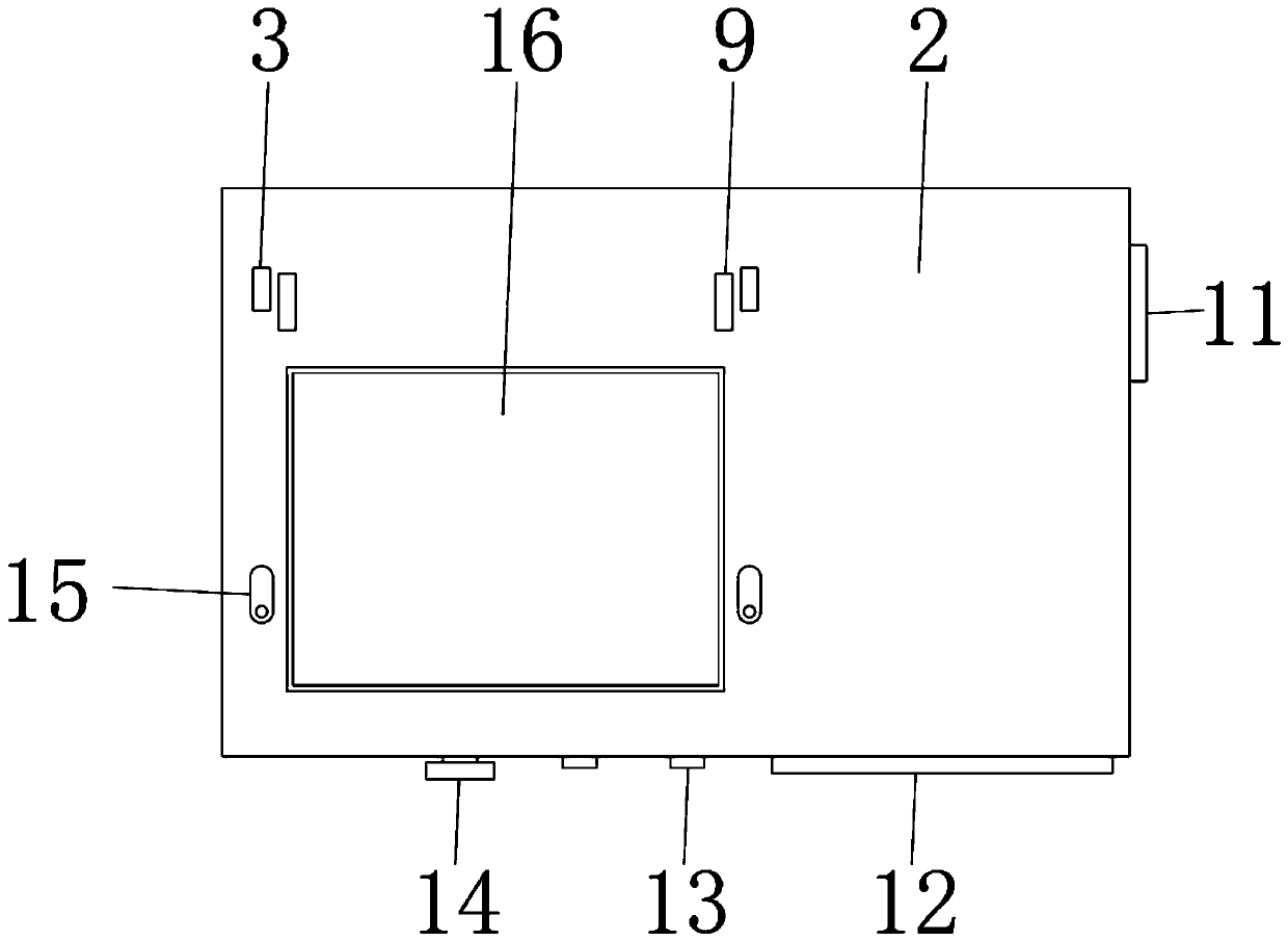
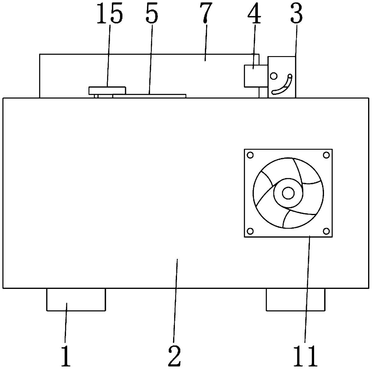
The invention discloses a vacuum heating bench. The bench comprises a shell, a cover plate, a touch screen and a heating plate. A cushion block is fixed to a surface of a bottom end of the shell. A touch screen is embedded in the surface of one side of the shell. An indicating lamp and a knob switch are embedded in one side, located on the touch screen, of the surface of the shell. A fan is fixedto a side end surface of one side of the shell. A heating plate is embedded in the surface of a top of the shell. A rubber pad is attached to an outer side of the heating plate. A first side plate anda second side plate are welded to positions, located on one side of the heating plate, of an upper surface of the shell. The cover plate is rotatably installed above the shell through the first sideplate and the second side plate, a clamping groove is arranged in the surface of the bottom end of the cover plate, and the size of the clamping groove is matched with the size of the rubber pad. Thebench has an advantage that a vacuum environment can be created during heating so that heat losses are reduced, and heating efficiency is improved.

Description

technical field [0001] The invention relates to the technical field of heating tables, in particular to a vacuum heating table. Background technique [0002] Microwave hybrid integrated circuits are developing towards high performance, high reliability, miniaturization, high uniformity and low cost, and put forward high requirements for chip welding technology. When interconnecting chips, components, etc. with carriers (such as substrates, shells, etc.), the main implementation methods are conductive adhesive bonding and eutectic welding. For high-end microwave frequencies or high microwave power, eutectic welding has the advantages of small resistivity, small thermal conductivity, small thermal resistance, low microwave loss, and high reliability. It is impossible to create a vacuum environment during heating, resulting in a large heat loss during heating, wasting energy, and the heating efficiency is low, and the heating takes a long time. Contents of the invention [...

Claims


Application Information

Patent Timeline
Patent Type & Authority Applications(China)
IPC IPC(8): H01L21/67
CPCH01L21/67103
Inventor 石乾彪冯浪
Owner PURBEST TECH CHENGDU CO LTD
Learn More