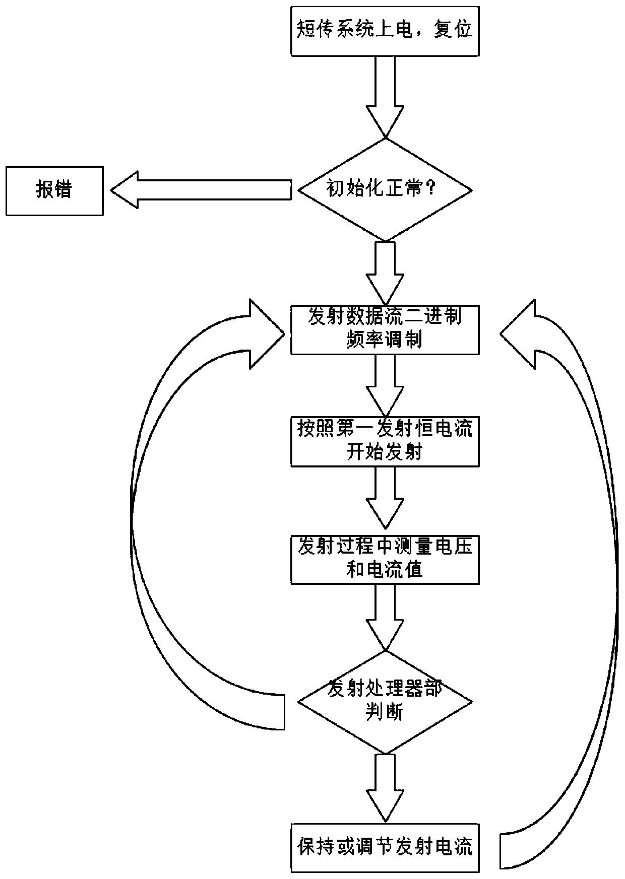
Near-bit wireless short pass constant current sending method and device
A constant current technology close to the drill bit, which is applied in the direction of earthwork drilling, measurement, borehole/well components, etc., can solve the problems of not using constant current emission technology, achieve great practical value, ensure stable power consumption, and avoid emission power consumption effect
- Summary
- Abstract
- Description
- Claims
- Application Information
AI Technical Summary
Problems solved by technology
Method used
Image
Examples
Embodiment 1
[0075] In the system that has been implemented so far, the power supply voltage is 11V, and the transmit processor part sets the maximum transmit current to 500mA. The system sets the collector voltage loaded to the PMOS through the DAC (analog-to-digital converter output port) of the processor part to 10V. . The power resistor is selected as Rs=2Ω, so if RL is less than 22 ohms, the maximum current loaded by the system to the H-bridge high-voltage terminal is 500mA ((11V-10V) / 2Ω). Since the discharge circuit current is 500mA, the power consumption loaded on the Rs power resistor is 0.5*0.5*2=0.5W, so Rs needs to use a high-power resistor to adapt to the situation where the current is above 500mA.
Embodiment 2
[0077] A higher emission current can be obtained by modifying the current system. The power supply voltage is 22V. The emission processor part sets the emission current to a maximum of 2A. The system is loaded to The collector voltage of the PMOS is 18V. The power resistor is selected as Rs=2Ω, so if RL is less than 11 ohms, the maximum current loaded by the system to the H-bridge high-voltage terminal is 2A ((22V-18V) / 2Ω). Since the discharge circuit current is 2A, the power consumption loaded on the Rs power resistor is 2*2*2=8W, so Rs needs to use a high-power resistor to adapt to the situation where the current is above 2A.
Embodiment 3
[0079] In the case of drilling with high resistivity, the power supply voltage is 11V, and the emission processor part sets the maximum emission current to 0.5A. The system loads the PMOS through the DAC (analog-to-digital converter output port) setting of the processor part. The collector voltage is 10V. The power resistor is selected as Rs=2Ω, so if RL is less than 22 ohms, the maximum current loaded by the system to the high voltage end of the H bridge is 2A ((22V-18V) / 2Ω). However, if the current equivalent resistance R at both ends of the emitter electrode is large, and the total load RL of the discharge circuit is greater than 22 ohms, then the discharge circuit works at a current of 11V / RL, and the current of the circuit at this time is less than 500mA.
PUM
 Abstract
Description
Claims
Application Information
 - R&D
- Intellectual Property
- Life Sciences
- Materials
- Tech Scout
- Unparalleled Data Quality
- Higher Quality Content
- 60% Fewer Hallucinations
Browse by: Latest US Patents, China's latest patents, Technical Efficacy Thesaurus, Application Domain, Technology Topic, Popular Technical Reports.
© 2025 PatSnap. All rights reserved.Legal|Privacy policy|Modern Slavery Act Transparency Statement|Sitemap|About US| Contact US: help@patsnap.com


