
Seamless contact rail system and connecting method of contact rail system

A technology of seamless connection and connection method, which is applied in the field of contact rail system, can solve problems such as misalignment of splicing surfaces, influence on vehicle flow quality, and decrease in fastening force of fasteners, so as to improve integrity and smoothness, and actively Social demonstration benefits and the effect of improving the environmental ecology along the line

Pending Publication Date: 2019-12-31
CHINA RAILWAY SIYUAN SURVEY & DESIGN GRP
View PDF0 Cites 0 Cited by
  • Summary
  • Abstract
  • Description
  • Claims
  • Application Information

AI Technical Summary

Problems solved by technology

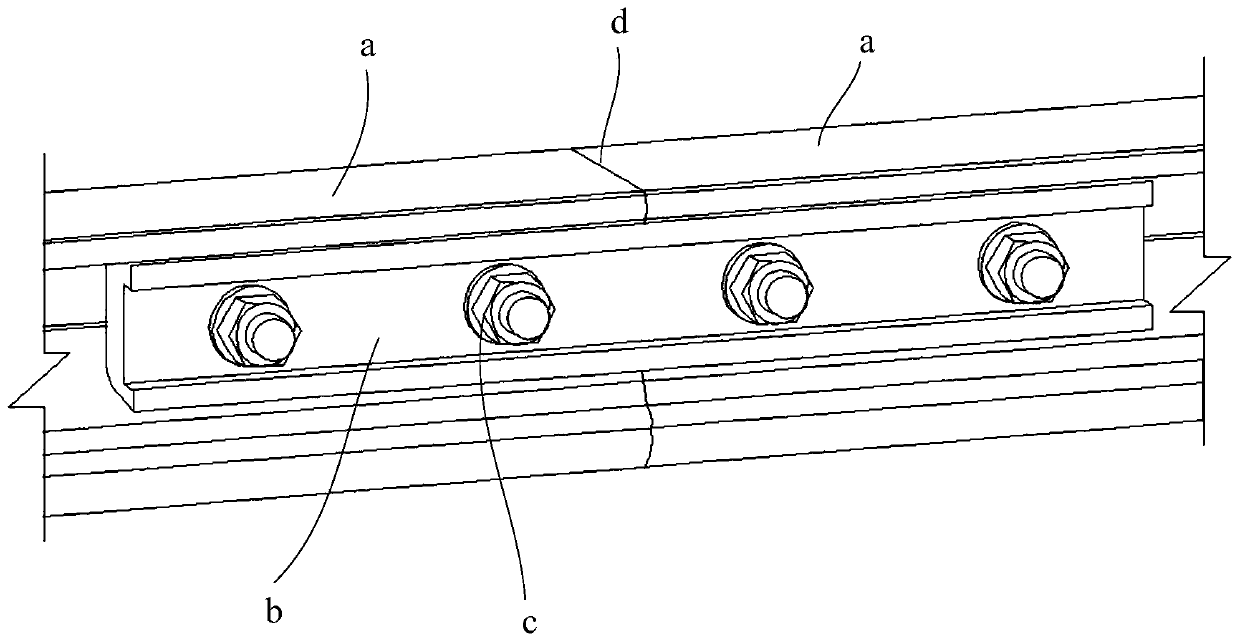
Using this kind of mechanical joint as a connecting piece will inevitably form a gap d at the joint, and the splicing surface will not be aligned due to errors in parts manufacturing and construction, resulting in vehicle current collectors (also known as collector shoes) The friction surface between the contact rail and the contact rail is not smooth, which affects the flow quality of the vehicle
[0003] Even if during the construction process, the joints are treated by replacing parts and grinding the joints, the smoothness requirements can be met temporarily, but usually the rail temperature changes in a large range, and in the operating environment of long-term frequent vibrations, the fasteners at the joints are extremely difficult. The fastening force is prone to decrease, resulting in loosening of the joint, and the unevenness of the flow transfer surface again.
Moreover, due to the large number of intermediate joint fasteners, coupled with the long line and short maintenance time, the maintenance of fasteners has caused greater work pressure to the operation
Therefore, the problem of uneven flow transfer surface is ubiquitous in rail engineering such as subways. If it is not paid attention to, it will cause "staggered platform" phenomenon on the contact rail flow transfer surface in severe cases. Generates a huge impact, causing equipment damage and threatening driving safety

Method used


Image

  • Seamless contact rail system and connecting method of contact rail system
  • Seamless contact rail system and connecting method of contact rail system
  • Seamless contact rail system and connecting method of contact rail system

Examples


Embodiment Construction

[0030] In order to make the purpose, technical solutions and advantages of the embodiments of the present invention more clear, the following will clearly and completely describe the technical solutions of the embodiments of the present invention in conjunction with the drawings of the embodiments of the present invention. Apparently, the described embodiments are some, not all, embodiments of the present invention. All other embodiments obtained by those skilled in the art based on the described embodiments of the present invention belong to the protection scope of the present invention.

[0031] In the description of the present invention, it should be understood that the orientation or positional relationship indicated by the terms "upper", "lower", "top", "bottom", "inner" and "outer" are based on the attached figure 2 And attached Figure 4 The orientation or positional relationship shown.

[0032] An embodiment of the present invention provides a seamless contact rail...


PUM


Abstract

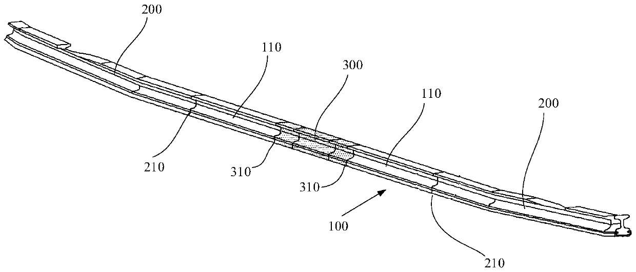
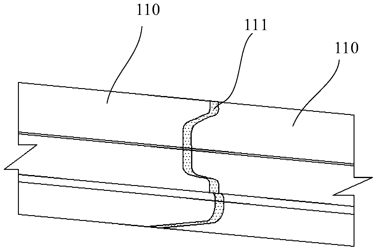
The invention discloses a seamless contact rail system and a connecting method of the contact rail system. The seamless contact rail system comprises multiple anchoring sections arranged in the line direction; each anchoring section comprises at least two current-carrying parts with current-carrying demands; and the two adjacent current-carrying parts are seamlessly connected with each other. According to the technical scheme of the embodiment of the invention, the use of a mechanical joint is avoided, and the operation workload is reduced. The integrity and smoothness of a contact rail are also improved, the dynamic characteristic between a collector shoe and the contact rail is improved, and the system and the method are beneficial for improving the current supplying quality and enhancing the adaptability to higher speed target value.

Description

technical field [0001] The invention relates to a contact rail system of rail transit, in particular to a seamless contact rail system and a connecting method of the contact rail system. Background technique [0002] Taking the connection of two adjacent contact rails as an example, along the line extension direction, two adjacent contact rails a are connected by mechanical joints, such as figure 1 As shown, the mechanical joint includes a fishplate b and a fastener c, and the fastener is generally a bolt. Using this kind of mechanical joint as a connecting piece will inevitably form a gap d at the joint, and the splicing surface will not be aligned due to errors in parts manufacturing and construction, resulting in vehicle current collectors (also known as collector shoes) The friction surface between the contact rail and the contact rail is not smooth, which affects the flow quality of the vehicle. [0003] Even if during the construction process, the joints are treated ...

Claims


Application Information

Patent Timeline
IPC IPC(8): B60M1/30B60M5/00
CPCB60M1/30B60M5/00
Inventor 戚广枫徐鸿燕单翀皞李红梅刘明杰吴江涛龚孟荣黄冬亮刘煜铖王璐
Owner CHINA RAILWAY SIYUAN SURVEY & DESIGN GRP
Learn More