
Carbon fiber composite mold surface forming property screening method

A composite material and surface molding technology, which is applied in the field of carbon fiber reinforced resin matrix composite material structure molding, can solve the single evaluation method of surface roughness, cannot realize comprehensive evaluation, and cannot meet the development needs of large-diameter high-precision composite antenna reflectors and other issues to achieve the effect of high reliability and shortened development cycle

Inactive Publication Date: 2019-12-31
BEIJING SATELLITE MFG FACTORY
View PDF3 Cites 1 Cited by
  • Summary
  • Abstract
  • Description
  • Claims
  • Application Information

AI Technical Summary

Problems solved by technology

[0005] However, at present, the surface accuracy of carbon fiber forming molds is mainly obtained by turning over the master mold. The limit accuracy that can be achieved by direct molding is about 0.05mm RMS, which still cannot meet the development needs of large-caliber high-precision composite antenna reflectors. Therefore, it is necessary to directly Grinding and polishing on the basis of forming accuracy to further improve the accuracy
The surface state of composite molds has a great influence on its forming performance, precision retention, and control of loss of mold release accuracy. Currently, it is confirmed that for the comprehensive evaluation criteria for the surface state of composite molding molds, existing evaluation methods such as surface roughness It is also relatively simple, and it is impossible to achieve a comprehensive evaluation of the surface of the composite material after grinding and polishing

Method used


Image

  • Carbon fiber composite mold surface forming property screening method

Examples


Embodiment Construction

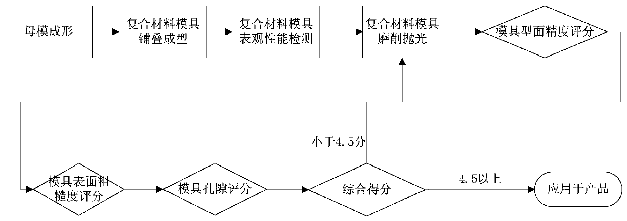
[0030] Such as figure 1 Shown, a kind of carbon fiber composite mold surface formability screening method of the present invention, the steps are as follows:

[0031] (1): CNC machine tools are used to process the master mold according to the parabolic equation to produce a molding surface with a certain surface accuracy and surface roughness;

[0032] (2): The mold prepreg is used to lay the mold on the surface of the master mold in step 1. During the prepreg laying process, the prepreg is prepressed according to the prepress system of the mold prepreg resin system; After the prepreg laying is completed, according to the curing system of the mold prepreg resin system, the curing and molding of the composite mold is completed in an autoclave or an oven;

[0033] (3): After the composite material mold completes the curing and molding of step 2 on the master mold, the composite material mold is released from the master mold to ensure that there is no layered cracking damage dur...


PUM


Abstract

The invention discloses a carbon fiber composite mold surface forming property screening method. The method comprises the specific steps that firstly, a numerical control machine tool is adopted for machining a forming surface on a female die; secondly, die prepreg is adopted to be laid on the surface of the female die in the first step, and after the prepreg is laid, according to the curing system of the die prepreg resin system, curing forming of a composite die in a hot pressing tank or oven can be finished; thirdly, the composite die is separated out of the female die, and is subjected tocold and hot circulation treatment, and point cloud information of the product profile is obtained, and is transmitted to a numerical control grinding and polishing machining system; fourthly, a high-spot material is removed, and after the profile precision is converge to the die profile precision threshold, a polishing device is adopted for carrying out circular polishing according to the profilefinal precision needs; and fifthly, a three-dimensional measuring method is adopted for carrying out comprehensive evaluation on the forming surface property. The comprehensive evaluation of the surface property after profile precision is improved through the grinding and polishing machining means of the carbon fiber composite die is achieved.

Description

technical field [0001] The invention belongs to the structural forming technology of carbon fiber reinforced resin matrix composite material, and is applied to the research and development of composite material antenna reflector structure products for spacecraft. Background technique [0002] The space-borne large-aperture composite antenna reflector is a typical carbon fiber-skinned honeycomb sandwich structure, which has the characteristics of light weight, high precision, and high thermal stability. Accuracy is also gradually improved. [0003] The molding of resin-based carbon fiber composite antenna reflector mainly refers to the carbon-skinned honeycomb sandwich structure. Two carbon fiber skins are glued and solidified with the end face of the honeycomb core through a molding die under high temperature and high pressure conditions to form a stable structure. At the same time, through the design of a special The mechanical interface is connected with the feed source a...

Claims


Application Information

Patent Timeline
IPC IPC(8): B29C33/38B29C70/34B29C70/54
CPCB29C33/3842B29C70/34B29C70/54
Inventor 刘佳张开虎周宓董丰路黎昱贾闽涛马立倪爱晶曾婷张夏明
Owner BEIJING SATELLITE MFG FACTORY
Learn More