Preparation process of explosion proof type magnetostrictive liquid level meter

A magnetostrictive liquid level and preparation process technology, which is applied in the direction of buoy liquid level indicators, etc., can solve the problems of a sharp increase in the cost of magnetostrictive liquid level gauges, very high straightness requirements for waveguide wires, and expensive imported waveguide wires. , to achieve good insulation, high hardness, and reduce storage space and length requirements

Active Publication Date: 2019-12-31
XIAN ANCN INTELLIGENT INSTR
View PDF3 Cites 4 Cited by
  • Summary
  • Abstract
  • Description
  • Claims
  • Application Information

AI Technical Summary

Problems solved by technology

However, in the installation of its sensor, due to the limitation of the process method, only imported waveguide wire can be used for production, and the straightness of the waveguide wire is very high, and the waveguide wire must be stored in a straight line when storing
For the flexible liquid level gauge, its length is distributed between 4 meters and 20 meters, and the imported waveguide wire can only be stored in a straight line with a length of 20 meters, which takes up a lot of space; storage and transportation are very inconvenient, and the imported waveguide wire is expensive, which is domestic The price of the waveguide wire is more than 10 times, so that the cost of the magnetostrictive liquid level gauge increases sharply

Method used


Image

  • Preparation process of explosion proof type magnetostrictive liquid level meter
  • Preparation process of explosion proof type magnetostrictive liquid level meter
  • Preparation process of explosion proof type magnetostrictive liquid level meter

Examples


Embodiment Construction

[0028] The present invention will be further described in detail below in conjunction with the drawings and embodiments:

[0029] The invention provides a preparation process of an explosion-proof magnetostrictive level gauge, which includes the following steps:

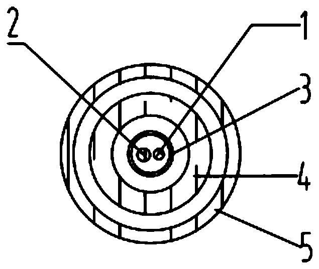
[0030] Step 1): Weld the waveguide wire 1 and the feeder line 2, weld one end of the waveguide wire 1 and the feeder line 2, and pass them into the inner protection tube 3 in parallel, and the solder joints of the waveguide wire 1 and the feeder line 2 are protected by a heat shrink tube;

[0031] Step 2): Insert the inner protective tube 3 into the corrugated tube 4, and then thread the corrugated tube 4 into the outer protective tube 5;

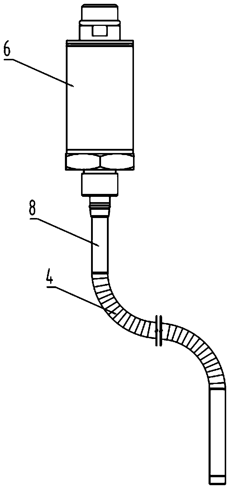
[0032] Step 3): The bellows 4 and the steel pipe 8 are welded, and the inner protection tube 3 and the electronic warehouse 6 are fixedly connected;

[0033] Step 4): Weld the steel pipe 8 and the electronic warehouse 6;

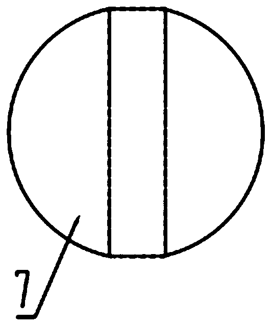
[0034] Step 5) Install the maglev ball 7 on the outside of the outer ...


PUM

PropertyMeasurementUnit
Magnetostriction coefficientaaaaaaaaaa
Diameteraaaaaaaaaa

Abstract

The invention belongs to the technical field of liquid level measurement and relates to a preparation process of an explosion proof type magnetostrictive liquid level meter. The preparation process comprises the following steps: welding a waveguide wire and a feeder, welding the waveguide wire to one end of the feeder, protecting a welding spot by a heat shrinkable tube and penetrating an inner protecting tube in parallel; penetrating the inner protecting tube into a corrugated pipe, and penetrating the corrugated pipe into an outer protecting tube; welding the corrugated pipe to a steel tube,and fixedly connecting the inner protecting tube to an electronic cabin; welding the steel tube to the electronic cabin; mounting a magnetic levitation ball on the outer side of the outer protectingtube, wherein the magnetic levitation ball is spherical, forming a columnar through hole in the center of the magnetic levitation ball, and mounting magnets in the columnar through hole, wherein the magnets and the columnar through hole are concentric, and the pole N of each magnet faces inward. By changing the protecting mode of the welding pot of the waveguide wire and the feeder, deformation ofthe waveguide wire at a low temperature can be prevented effectively and a stress effect between the inner protecting tubes can be prevented effectively. By designing a mounting structure and a distributing shape of the magnets, each magnet is mounted in a manner that the pole N faces inward, so that the vibrating amplitude of a torsional wave of the waveguide wire is enhanced and the echo signalamplitude is improved.

Description

Technical field [0001] The invention belongs to the technical field of liquid level measurement, relates to a preparation process of a liquid level gauge, in particular to a preparation process of an explosion-proof magnetostrictive liquid level gauge. Background technique [0002] In the flammable and explosive environment such as petroleum and natural gas exploration and petrochemical industry, the measurement of oil volume in oil tanks is mostly carried out by manually climbing the tank and measuring with a ruler. Use a metric steel tape measure with a heavy hammer or a scaled ruler to measure, manually record the readings, and manually check the meter for conversion, and finally get the oil volume data. This measurement method is not only labor intensive, but also has unsafe factors and cannot guarantee accuracy. [0003] Several existing level gauges mainly include: ①Capacitive and diffused silicon pressure level gauges. These sensors have serious zero drift, large measuremen...

Claims


Application Information

Patent Timeline
IPC IPC(8): B23P15/00G01F23/62
CPCB23P15/00G01F23/62
Inventor 王士兴官军昌
Owner XIAN ANCN INTELLIGENT INSTR
Why Eureka
Try Eureka