High-adaptability worm-gear speed reducer with needle gear shell structure and casting method

A technology of worm gear and pin gear housing, which is applied to components with teeth, belts/chains/gears, gear transmissions, etc. It can solve the problem of fixed transmission ratio, poor versatility, and inability to directly install worm gear reducers, etc. problem, achieve the effect of avoiding no-load and strong versatility

Inactive Publication Date: 2019-12-27
杭州新融方科技有限公司
View PDF0 Cites 0 Cited by
  • Summary
  • Abstract
  • Description
  • Claims
  • Application Information

AI Technical Summary

Problems solved by technology

[0005] Aiming at the deficiencies of the prior art, the present invention provides a highly adaptable worm gear reducer with a pin gear housing structure and a casting method, which solves the problem that the existing worm gear reducer generally only has a set of internal worm gears for transmission, and the transmission ratio Fixed, and then can only achieve the specified deceleration effect, the versatility is not strong, and for some installation environments where the installation space is limited or the position of the driving shaft and the driven shaft do not match the conventional worm gear reducer, the conventional worm gear reducer cannot be directly installed The problem

Method used


Image

  • High-adaptability worm-gear speed reducer with needle gear shell structure and casting method
  • High-adaptability worm-gear speed reducer with needle gear shell structure and casting method
  • High-adaptability worm-gear speed reducer with needle gear shell structure and casting method

Examples


Embodiment Construction

[0039] The technical solutions in the embodiments of the present invention will be clearly and completely described below with reference to the accompanying drawings in the embodiments of the present invention. Obviously, the described embodiments are only a part of the embodiments of the present invention, but not all of the embodiments. Based on the embodiments of the present invention, all other embodiments obtained by those of ordinary skill in the art without creative efforts shall fall within the protection scope of the present invention.

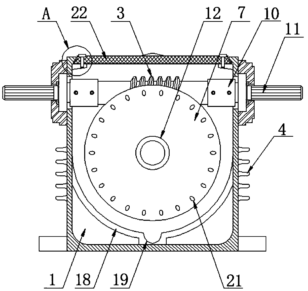
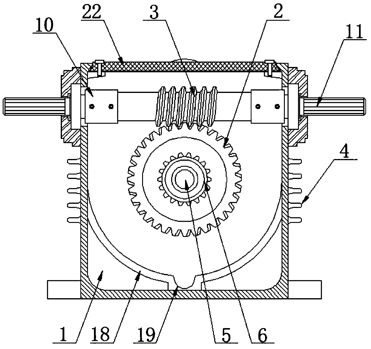
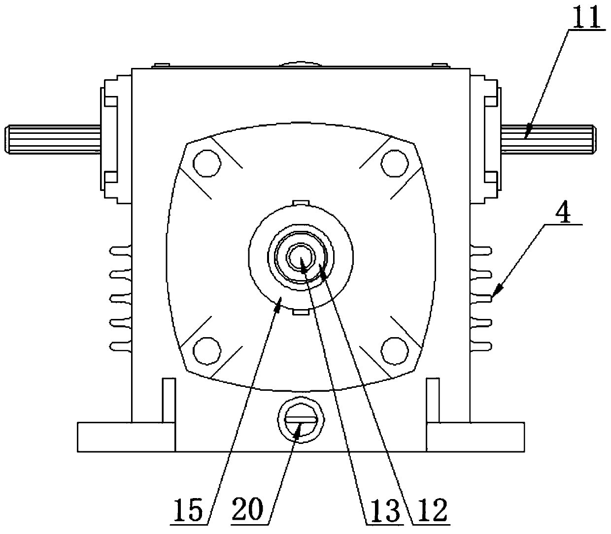
[0040] see Figure 1-8 , the embodiment of the present invention provides a technical solution: a highly adaptable worm gear reducer with a pintooth housing structure, including a housing 1, the front and rear sides of the housing 1 and the outside of the second fixed sleeve 12 are fixedly connected Positioning sleeve 15 is arranged, and the internal thread of positioning sleeve 15 is connected with positioning pin 24, and one end of ...


PUM


Abstract

The invention discloses a high-adaptability worm-gear speed reducer with a needle gear shell structure, and relates to the technical field of worm-gear speed reducers. The speed reducer comprises a shell, wherein a worm wheel is arranged in the middle of the inside of the shell, the top of the inner surface of the shell is rotatably connected with a worm, and the surface of the worm meshes with the worm wheel. According to the high-adaptability worm-gear speed reducer with the needle gear shell structure, on the basis of the traditional speed change transmission of the worm wheel and the worm,a planetary gear speed change mechanism composed of a needle gear shell, a planetary gear and a central gear is additionally arranged, and transmission shafts are arranged at the left end and the right end of the worm, the center of a circle of the front surface of the needle gear shell and the center of a circle of the back surface of the worm wheel, so that the speed reducer has multiple speedreduction effects; and different mounting effects are realized by connecting a driving shaft and a driven shaft to the different transmission shafts, the requirements of mounting positions of the different shafts are met by selecting the different transmission shafts, the transmission effect that multiple components are driven by one transmission shaft is realized, and adaptability of the speed reducer is high.

Description

technical field [0001] The invention relates to the technical field of worm gear reducers, in particular to a highly adaptable worm gear reducer with a pin tooth shell structure and a casting method. Background technique [0002] The worm gear reducer is a power transmission mechanism that uses the speed converter of the gear to reduce the number of revolutions of the motor (motor) to the desired number of revolutions and obtain a larger torque. In the mechanism used to transmit power and motion, the application range of reducer is quite extensive. Its traces can be seen in the transmission system of all kinds of machinery, from ships, automobiles, locomotives, heavy machinery for construction, processing machinery and automatic production equipment used in the machinery industry, to common household appliances in daily life. , clocks, etc. The application of the reducer can be seen from the transmission of large power to the transmission of small loads and precise angle. ...

Claims


Application Information

Patent Timeline
IPC IPC(8): F16H37/04F16H57/023F16H57/031F16H57/039F16H57/08B22C9/02B22C9/22
CPCB22C9/02B22C9/22F16H37/046F16H57/023F16H57/031F16H57/039F16H57/08F16H2001/327F16H2055/176F16H2057/02017
Inventor 管晟琦管凯华
Owner 杭州新融方科技有限公司
Why Eureka
Try Eureka